How to doping Gillier Pantone water? Hoses and fittings
This page is part of the dossier ofhelp to carry out a Gillier Pantone water doping.
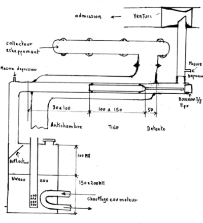
The description refers to the plan:

Click to enlarge
1) The output of the reactor must be conducted with a heat-resistant it can reach 300 ° C but usually it is in the vicinity of 100 ° C.
2) The pipe length is less critical than that between the bubbler and the reactor which must be as short as possible. This pipe must have the same diameter as the entry to avoid restrictions.
3) The ducts can be in any material, even the outlet duct could be insulated at least on one side it can also be in hydraulic pipe provided that it resists heat and that the depression does not crush it not. A lot of assemblies use copper because it bends well and it is not (too) expensive and available everywhere.
4) Obviously, the entire line of the system: bubbler-reactor-duct must be perfectly sealed, and this particularly at the outlet of the reactor. This duct opens into a venturi placed on the engine intake.
Connection to motor
1) A suction venturi is placed in the inlet duct in order to promote the suction of the gases. The venturi must have a diameter large enough not to restrict the inlet. Its design does not need to be very precise, it suffices to make a short convergent angle of 30 ° and a longer divergent of 7 °.
The wide Tolerence is a good venturi especially to less restriction, but for sucking, a rustic building will not lose a lot of efficiency. More details about this page: build an ideal venturi
2) is very easy with a dip tube in a water récipent in contrbas to see how high he can siphon
This venturi allows a good control on the reactor: the depression is almost proportional to the air downstream of the engine for a wide speed range. This allows to have at 2 3 times more depression in the reactor that without venturi.
3) on the inlet pipe and outlet of the reactor, it is possible to put pressure taps (small pipe welded 3mm) to make measurements.
The depression at the reactor inlet should be 200mm of water and more (for a height of 200mm of water in the bubbler obviously). The depression at the outlet of the reactor should be 700mm of water and more depending on the engine speed.
Learn more

