How to make a Gillier Pantone reactor for water injection in Diesel engines?
This page is part of the dossier ofhelp to carry out a Gillier Pantone water doping.
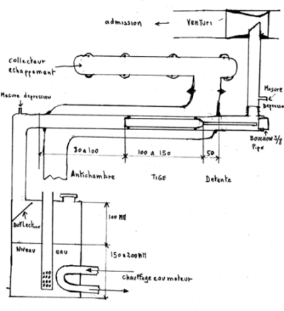
The description refers to the plan:

Click to enlarge
1) The reactor is placed as close as possible to the exhaust manifold. To recover as much heat as possible, it is preferable on turbo diesel to place a small deflector, in order to channel the exhaust gases around the front part of the reactor (steam outlet).
This deflector is linear, it is just a ring which channels the exhaust gases around the start of the reactor over a distance of 1/4 to 1/3 the length of the reactor, like a tube flared at the start and flared at the outlet (long venturi) with a reduced passage so that all the exhaust gases are throttled on this part, not too long in order to create the least possible restriction.
Please note: no spiral deflector, this slows down the passage of exhaust gases too much and gives no advantage at this level: the temperature drop is so sudden and localized when the reactor is operating that there is no point in let the exhaust gases stagnate around the reactor.
2) The reactor tube is made of stainless steel. It is welded into the exhaust pipe, the ends can be threaded or tapped.
The usual diameter of the inner tube of the reactor is 1 / 2 inch, 15 16 mm was inside, but other dimensions may be suitable. Ensure that the clearance between the rod and tube either to 1 1,5 mm.
3) The rod is made of stainless steel and its diameter is normally 13 mm. But it can be adapted to the diameter of the inner tube of the reactor in order to have a game has 1 1,5 mm. The length of the shaft varies in 100 150 mm for doping water. More powerful the motor over the rod can be shorter.
4) At the outgoing end of the reactor, a 3/8 or 1/2 threaded plug allows inspection and possible replacement of the rod.
5) The diameter of the outer tube after the restriction, it aims to conserve the original section of the exhaust tube around the reactor.
6) The entrance of the stem is cut at right angles, and its output is rounded or slightly profiled. Welded or screwed a rod 4 mm at the end: it is a spacer that joins the cap (4).
7) The spacer is intended to position the rod: it always ends up taking the game with expansion and vibration, and it behaves like a piston in the tube, drawn forward by suction. Without the spacer, the rod would eventually clog the exit hole of the reactor gas ...
8) Center of upper: 3 solder pads is achieved "in depth" to 120 2 degrees to the ends of the rod. Then lime (or better in round) adjusting the soldering points so that the rod between just clamped and better centered in the tube as possible. [I] Please do not do bad 'balls' of welding, which can break off and join the engine! [/ I]
9) Concerning the electrical insulation, 2 insulated rods were tested: - One with ceramic nozzles of TIG welding nozzle. This was complicated to do and did not withstand the vibration for long. - The other is a steel rod on which Teflon plumbing tape has been wound, to then force it into a stainless steel tube. Then I welded the centering nipples on the steel rod, so the insulation of the stainless steel tube (measured with a Fluke multimeter) was very good. In testing I didn't notice a big difference in running on fuel oil or 30% old frying oil, as I usually use.
10) Antechamber: the rod is positioned so as to have an anteroom of 80 to 100 mm, this conditions the steam before reaching the rod. This anteroom can be shorter with a bubbler, it must be longer for a carburetor or a water injector, because the water is less sprayed than with a bubbler.
The antechamber is very large on my experimental set-up, it allows me to walk with fuel oil without heating the liquid or the intake air. This absorbs almost all the temperature of the exhaust, which becomes cold: it can be held with bare hands while the engine is running. It is thanks to this disproportionate anteroom that I managed to operate with a high ratio of fuel oil and engine oil.
11) The expansion chamber should be in the hottest part of the exhaust, if possible in an elbow. Normally a length equal to the diameter of the exhaust duct is sufficient.
The relaxation room is important. Its purpose is to increase the temperature of the mixture in the reactor. This is the point that heats the most in the reactor, even more than on the large diameter of the rod. I have some questions about this… - How can the small spacer rod heat up more than the large one which is 1 mm from the wall? - How is it that the thermocouple welded on the exhaust tube in this place, is hotter at the end of the big rod? Indeed; if we move the rod, this hot point, measured on the exhaust side, seems to follow the end of the rod!
This suggests that heat is produced as the gases leave the rod and enter a less restricted chamber. It happens over a short distance. By running the engine without reactor insulation, this hot part is clearly visible: no need for a thermocouple.
The usefulness of this chamber is not yet well understood, but these facts are easily reproducible ...


hello, i want to make some kind of mixed reactor with generator together, that reactor together with generator to create electric power thanks.