Hi everybody,
here is a long time that I want to install a pantone system on my
truck (a mercedes, which has the same engine as the reaction group 220d
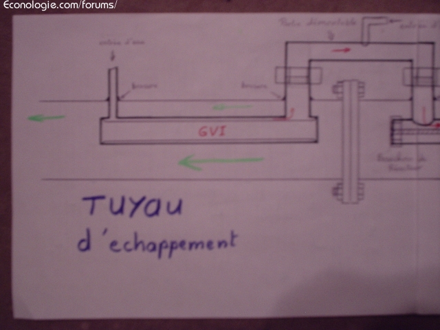
I think I will do the same GVI that I will integrate into the
exhaust pipe without modifying it (apart from the two entry holes
and water outlet).
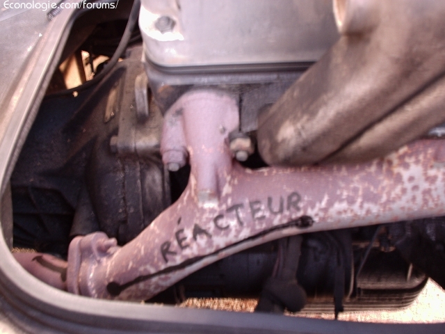
As for the reactor part, I think I just put it on the
engine exhaust outlet (I think it's a cast iron part but
I'm not sure), and install it as the GVI with two holes and
welding.by cons as it is before an exhaust light I
asks if it will not interfere with the operation of the engine because there is no
would not have the same clearance for the gas ???
Otherwise for the dimensions I have on hand a diameter 8mm rod
stainless steel waste (it was in a bucket with kitchen equipment, so
I do not know what kind of stainless steel it is exactly, is it important?).
think to cut it to 15cm.
For the tube, same provenance and it is 9mm of inner diameter and
12mm outside. I think to leave 3cm more on each side than the stem,
which gives 21cm.
For copper or hose connections I do not know what is best
and if there are diameters to respect?
For transplanting on admission I have two solutions:
-as the one of direct reaction in four points.
-or a little further upstream on the hose in one point.
here I made some pictures to get an idea of the thing,
to your critics and has more
Rome
photos to follow
pantone doping Mercedes MB100 (meme that 220d)
pantone doping Mercedes MB100 (meme that 220d)
Last edited by ROM1 the 22 / 10 / 09, 12: 40, 2 edited once.
0 x


Re: PANTONE ON MERCEDES
Hello Rom1, Welcome to the club! 
When the outputs are symmetrical this does not help the cyclical regularity of the engine, but .... only a real test will really tell you if it's an acceptable compromise or a stupidity.
- The stainless steel material or scrap makes no difference that in the rust apparently.
- It's diameters much smaller than what we could see on Econology. André? Did you try something of the style?
There are two schools that work, I'm not sure this is a very important parameter. For the inner diameters of these pipes, I guess the best compromise is in the range 10 to 15 mm.
This parameter seems to me more important, you're lucky, you must be able to easily make the 2 types of connection to your intake manifold. What is good on one engine may be bad on another (volumes, length, temperatures, turbulence are not the same.)
A+
ROM1 wrote:... and install it like the GVI with two holes and
welding.par cons as it is before an exhaust light I wonder if it will not disrupt the operation of the engine because there would not be the same clearance for gas ???
When the outputs are symmetrical this does not help the cyclical regularity of the engine, but .... only a real test will really tell you if it's an acceptable compromise or a stupidity.
Otherwise for the dimensions I have on hand a diameter 8mm rod
stainless steel waste (it was in a bucket with kitchen equipment, so
I do not know what kind of stainless steel it is exactly, is it important?).
think to cut it to 15cm.
For the tube, same provenance and it is 9mm of inner diameter and
12mm outside. I think to leave 3cm more on each side than the stem,
which gives 21cm.
- The stainless steel material or scrap makes no difference that in the rust apparently.
- It's diameters much smaller than what we could see on Econology. André? Did you try something of the style?
For copper or hose connections I do not know what is the best and if there are diameters to respect?
There are two schools that work, I'm not sure this is a very important parameter. For the inner diameters of these pipes, I guess the best compromise is in the range 10 to 15 mm.
For transplanting on admission I have two solutions:
-as the one of direct reaction in four points.
-or a little further upstream on the hose in one point.
This parameter seems to me more important, you're lucky, you must be able to easily make the 2 types of connection to your intake manifold. What is good on one engine may be bad on another (volumes, length, temperatures, turbulence are not the same.)
A+
0 x
Reason is the madness of the strongest. The reason for the less strong it is madness.
[Eugène Ionesco]
http://www.editions-harmattan.fr/index. ... te&no=4132
[Eugène Ionesco]
http://www.editions-harmattan.fr/index. ... te&no=4132
Hello to you
thank you for your encouragement, Flytox I don't quite understand when you say "the outputs are symmetrical".
After the diameter of the fittings I think I will stay between the diameter of the GVI and the diameter of the tube reactor. The thing I wonder is what diameter at which place?
Oh and something else too, if I do a transplant in 4 points on the admission, since it is an aluminum piece I can not solder so if there are some who have a thing I am open to ideas .. .
here I am in Toulouse at this time so if there are some who have already done and have time I have ....
a +
0 x
Hello
just my opinion about this montage
First do not touch the melting of the collector if you are not equipped to weld the brewing (dilation of the rigid rod in the cast iron can break it)
put your tube just below it in the small S (like the drawing GV) you can put across a standard pipe of 1 / 2 pipe spun on both sides and soda in this pipe
Since it is a permanent job, find yourself a stainless steel tube if possible.
Then find yourself a stainless steel rod adjusted to your tube the game there is a good tolerance of 0,8 mm to 1,2 mm
8mm of stem seems small? (I have 19mm on the Mercedes 300D and 12,7 mm on the Chevrolet)
In general the standard of the rods is 12,7 mm (1/2 inch this fits exactly in a 1/2 "pipe according to the thickness of the reactor
The length 150mmm has 200mm you can play around these numbers 100mm is a minum.
Drill a hole in the intake manifold (aluminum) just in front of the oil breather hole make 3/8 pipe threads and screw in a connector, connect this with a simple 3/8 "copper pipe, (I can't say if you make an entry in each cylinder if the differrence is large (I have not tried) I opt for simplicity of construction ..
A copper tube first it gets hot sometimes 200c in my case for electrical insulation? after an 1000km the interior of the conduit and the stem becomes covered with a gray layer
You will decide if you make GV, bubbler or other, anyway you have room on the duct escapes that decay and you are close to the entrance of the reactor.
efficiency depends on a lot of the input to the reactor
Keep in mind to build an easy assembly and to be able to make modifications easily, the stem accessible, although it is not at the level of the rod that you will make the most change, once installed you almost do not touch , once by 30 000km possible to remove the tartar if you walk with hard water (the tube tube air gap becomes very long very small it reduces the passage of moist air)
Do not discourage the first 1000km the performance remains quite mediocre, so do not change too much at first, it becomes good after you see appear the gray layer in the copper conduit entering the engine.
Andre
0 x
ROM1 wrote: Flytox I don't quite understand when you say "the outputs are symmetrical".
I expressed myself badly, what I wanted to say is that if in the exhaust manifold you place a new obstacle (your engine) it is not equidistant from each exhaust valve, and it does not present the same pressure drop for each exhaust outlet of each cylinder. The previous compromise (acoustic and flow) of the manufacturer, can be troubled and you can possibly lose torque on a particular cylinder at such or such operating regime, or even create a resonance more or less harmful to the filling of the engine. In fact, when you modify a pot, it's easier to degrade the performance than to increase it.
After the diameter of the fittings I think I will stay between the diameter of the GVI and the diameter of the tube reactor. The thing I wonder is what diameter at which place?
When the pipe diameter is too big, the steam cools faster (bad at low speed / load!?). When the pipe is too small, the pressure loss increases a lot and the gas goes much faster inside (not sure that it is very good
Oh and something else too, if I do a transplant in 4 points on the admission, since it is an aluminum piece I can not solder so if there are some who have a thing I am open to ideas .. .
For the assembly on my R19 with an aluminum alloy intake manifold, I made with a 12 mm diameter copper inserted "in force" into the aluminum and to make it hold I modeled with the outside against the copper, a small resin pyramid about 10 to 15 mm high with this kind of product. Apparently it holds the temperature, the steam etc ... for> 15000 km
A+


0 x
Reason is the madness of the strongest. The reason for the less strong it is madness.
[Eugène Ionesco]
http://www.editions-harmattan.fr/index. ... te&no=4132
[Eugène Ionesco]
http://www.editions-harmattan.fr/index. ... te&no=4132
Hello to you
for André:
I think that I will be able to braze the reactor and not to weld it (does the solder allow the expansion?), and in this case I renew my question with respect to the place of the reactor in front of one of the exhaust lights, is it may disrupt engine performance as suggested by flytox.
There is no turbo on my truck and I am at the moment for the grouping of information and gear to avoid making mistakes already made by others.De more like it's my vehicle I can not afford to put it on the road.I would like to have a margin of error quite small in my realization.and as it is not a vehicle that runs the breaks I do not really want to buy big new engine parts.
Here are the reasons for these questions a little fussy.
For the reactor I will try to find a larger diameter but it is not obvious I already have a lot of research and that's all I find.
Otherwise for the assembly I have the impression that you are describing an assembly as we have seen in all the other achievements, with a tube (for the reactor chamber) welded across the exhaust line, whereas what I imagined it is to insert the reactor part in the exhaust manifold in the same way as I insert the gvi in the exhaust tube (it will be like that a quick and simple assembly 4 holes and 4 solders ) unless you confirm flytox for the first remark, in this case I will do the "traditional" assembly.
and for transplanting from what I've read in all your exchanges of the site is best to transplant as close as possible to the admission, so I think I will transplant into 4 points as the merco of direct reaction even if it's a little more work, if this is the optimum it seems to me feasible with the means that I have.
a +
rom
I will make a diagram of how I see the thing ...
for André:
First do not touch the melting of the manifold if you are not equipped to solder the solder (dilation of the rigid rod in the cast iron can break it)
I think that I will be able to braze the reactor and not to weld it (does the solder allow the expansion?), and in this case I renew my question with respect to the place of the reactor in front of one of the exhaust lights, is it may disrupt engine performance as suggested by flytox.
Have you made a comparison between entering a single duct in the intake and a multi duct just at the breech?
Because those who work with turbo is rather far ahead of the turbo ..
There is no turbo on my truck and I am at the moment for the grouping of information and gear to avoid making mistakes already made by others.De more like it's my vehicle I can not afford to put it on the road.I would like to have a margin of error quite small in my realization.and as it is not a vehicle that runs the breaks I do not really want to buy big new engine parts.
Here are the reasons for these questions a little fussy.
For the reactor I will try to find a larger diameter but it is not obvious I already have a lot of research and that's all I find.
Otherwise for the assembly I have the impression that you are describing an assembly as we have seen in all the other achievements, with a tube (for the reactor chamber) welded across the exhaust line, whereas what I imagined it is to insert the reactor part in the exhaust manifold in the same way as I insert the gvi in the exhaust tube (it will be like that a quick and simple assembly 4 holes and 4 solders ) unless you confirm flytox for the first remark, in this case I will do the "traditional" assembly.
and for transplanting from what I've read in all your exchanges of the site is best to transplant as close as possible to the admission, so I think I will transplant into 4 points as the merco of direct reaction even if it's a little more work, if this is the optimum it seems to me feasible with the means that I have.
a +
rom
I will make a diagram of how I see the thing ...
0 x

-
- Similar topics
- Replies
- views
- Last message
-
- 14 Replies
- 8221 views
-
Last message by GuyGadeboisTheBack
View the latest post
22/11/21, 11:38A subject posted in the forum : Water injection in engines: montages and experiments
-
- 6 Replies
- 8935 views
-
Last message by kestjc
View the latest post
11/11/21, 17:39A subject posted in the forum : Water injection in engines: montages and experiments
-
- 6 Replies
- 8850 views
-
Last message by denis
View the latest post
08/07/19, 15:09A subject posted in the forum : Water injection in engines: montages and experiments
-
- 19 Replies
- 21860 views
-
Last message by Flytox
View the latest post
14/12/17, 23:04A subject posted in the forum : Water injection in engines: montages and experiments
-
- 51 Replies
- 64672 views
-
Last message by chris59
View the latest post
19/08/13, 12:02A subject posted in the forum : Water injection in engines: montages and experiments
Back to "Water injection in the engines: the assembly and experimentation"
Who is online ?
Users browsing this forum : No registered users and 138 guests