The 4 cylinders are connected by separate tubes.
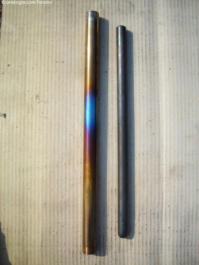
The new exhaust pipes are 2.5 inches (6.5 cm) in diameter. concerning the reactor it is 40 cm long !!! 21 mm stainless steel tube inside and 19 mm reactor rod ... more by what I had the place than by conviction but as the heat exchange seemed an important factor I told myself that on this length the steam would have time warm well and spin around the stem ...
I will try to find silicone hoses, if not too expensive !!!
Need advice for Gillier-pantone mounting petrol

Yael wrote:The 4 cylinders are connected by separate tubes.
The new exhaust pipes are 2.5 inches (6.5 cm) in diameter. concerning the reactor it is 40 cm long !!! 21 mm stainless steel tube inside and 19 mm reactor rod ... more by what I had the place than by conviction but as the heat exchange seemed an important factor I told myself that on this length the steam would have time warm well and spin around the stem ...
A 40 cm rod seems a bit long (30 cm max?). André what do you think? You risk increasing the pressure drop in the exhaust a little too much without increasing the efficiency of the reactor.
Yael wrote:
I will try to find silicone hoses, if not too expensive !!!
We find it in detail, .... fortunately, because if you buy a 25 m roll ... you will break the piggy bank ...
0 x
Reason is the madness of the strongest. The reason for the less strong it is madness.
[Eugène Ionesco]
http://www.editions-harmattan.fr/index. ... te&no=4132
[Eugène Ionesco]
http://www.editions-harmattan.fr/index. ... te&no=4132
yes I know that it is a little long but as we can see it on the assembly the outside tube of the reactor this prolongs to leave above the engine block and thus to be just in front of the air inlets of the carburetor, at most for not to lose heat, it is for convenience of assembly that I did that but obviously we can put a rod of the length that we want ...
Look in the photo, the hottest point on the reactor (because opposite the exhaust outlets) is around the middle of the reactor. The rod probably does not need to continue beyond this point is it?
Look in the photo, the hottest point on the reactor (because opposite the exhaust outlets) is around the middle of the reactor. The rod probably does not need to continue beyond this point is it?
0 x
Where there is a will there is way.
Or there is a will there is a way.
Or there is a will there is a way.
I am not very wealthy in carburetor operation, who could light my lantern on these points? :
1
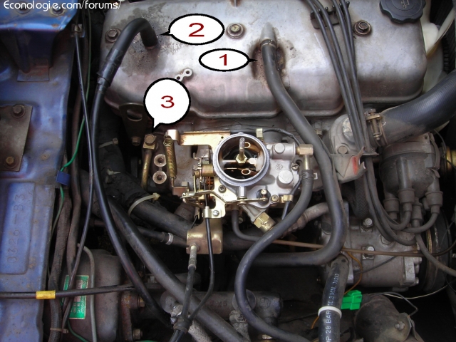
it is a priori an air intake for the vapors of oils and it is connected to the air intake after the fuel. By disconnecting it from the cylinder head cover I could feel that there was a strong suction at low and high engine speed ... It sucks the finger like a vacuum cleaner and by plugging it it does not seem to affect the engine either .
2
it is the air intake of oil vapors which is connected to the fuel inlet after the air filter in fact. Not really of suction since if I the mouth, the air enters by the large entry with the air filter.
Do I connect the reactor outlet with 1, or 2, or even both for a strong suction ???
Besides, I don't know why there are two air intakes for the oil vapors ???
3
is connected to the brake master cylinder. Why already? is it air or a liquid that is in this metal "hose"?
1
it is a priori an air intake for the vapors of oils and it is connected to the air intake after the fuel. By disconnecting it from the cylinder head cover I could feel that there was a strong suction at low and high engine speed ... It sucks the finger like a vacuum cleaner and by plugging it it does not seem to affect the engine either .
2
it is the air intake of oil vapors which is connected to the fuel inlet after the air filter in fact. Not really of suction since if I the mouth, the air enters by the large entry with the air filter.
Do I connect the reactor outlet with 1, or 2, or even both for a strong suction ???
Besides, I don't know why there are two air intakes for the oil vapors ???
3
is connected to the brake master cylinder. Why already? is it air or a liquid that is in this metal "hose"?
0 x
Where there is a will there is way.
Or there is a will there is a way.
Or there is a will there is a way.
Yael wrote:1
it is a priori an air intake for the vapors of oils and it is connected to the air intake after the fuel. By disconnecting it from the cylinder head cover I could feel that there was a strong suction at low and high engine speed ... It sucks the finger like a vacuum cleaner and by plugging it it does not seem to affect the engine either .
It is a good place to connect the steam supply.
2
it is the air intake of oil vapors which is connected to the fuel inlet after the air filter in fact. Not really of suction since if I the mouth, the air enters by the large entry with the air filter.
Chai not too much what it is for. To limit the depression in the rocker cover when the throttle is in the almost closed position?
3
is connected to the brake master cylinder. Why already? is it air or a liquid that is in this metal "hose"?
Your brake assist also works with the intake air depression. This increases the braking effort by a membrane which pushes the piston of the master cylinder.
0 x
Reason is the madness of the strongest. The reason for the less strong it is madness.
[Eugène Ionesco]
http://www.editions-harmattan.fr/index. ... te&no=4132
[Eugène Ionesco]
http://www.editions-harmattan.fr/index. ... te&no=4132
Hello
Nice editing it remains to develop it.
Next to the rod and tube photos? (never seen a black rod like that on a doping with water, yes sometimes on petrol pants) I have the impression that the assembly worked without any circulation or very weak of vapor
The centering nipples look very small to me (is there 1mm of air gap?) Mm all around the rod too tight this limits the passage a fortiori if the rod is long
The hottest point on the reactor tube is where it meets the exhaust pipes, the reactor rod outlet must end at this point, the length of the reactor tube is not very important, the rod is no longer there, at the beginning I used 300mm rods now from 220 to 250mm, the internal position of the reactor is more important, leave a chamber in front of the rod, and a shorter one at the rod exit.
What enters the reactor must be steam, mist made of water particles, and warm air.
On an auto gasoline engine I never managed to operate by entering in front of the carburetor, I enter the intake manifold in the high vacuum, but with a nozzle from 2 to 3,2 mm placed at the reactor inlet.
entry problems in the manifold under the throttle valve:
At idle too much vacuum too much steam suck into the reactor
This entry of steam and air increases the slowdown
This input, at low speed is too important for regulating the system too much steam, and at high speed high power less vacuum, not enough steam.
So with a calibrated nozzle, you arrive at a good adjustment for a certain regime (100kmh in my case) at 140km you lack steam at 60kmh you have too much steam, despite this defect of regulation you arrive in a simple way to a good compromise for usual speeds of 80 to 120kmh
the other settings are the air and steam ratio which enters the reactor (rather tolerate an excess of air rather than steam)
The advantages of entering under the butterfly:
High vacuum, simplicity of construction, and adjustment of a simple nozzle, easy to enter the engine.
the biggest advantage is the entry of steam which does not pass through the venturi of the carburetor and therefore does not enrich the mixture. On the other hand the air which passes in the reactor, makes the mixture slightly leaner and it is necessary when one functions in doping with water
(verified by numerous experiences with electronic injection)
The mounting on my 5,5 liter Lycoming aircraft, still in charge, was above the carburetor, but difficult to have a good pressure.
the outlet of the reactor, a simple 3/8 "copper pipe is functional, after a 500 to 1000 km if you use hard water the pipe becomes completely isolated, the internal temperature of the outlet gases rises to around 180 to 200C
For the engine photo
The output 1 is the oil vapors drawn from the crankcase. This goes into a PCV valve a valve, or certain engine a small 2mm hole to suck the oil and water vapors from the crankcase.
The outlet 2 is the inlet air for the crankcase ventilation. It is taken between the carburetor and the air filter. This makes a sort of flow of air ventilation in the crankcase.
Line 3 is the vacuum connection in the intake manifold for the assisted brakes.
If you have a not too old engine, you must block the ERG valve and use it to enter the steam from the reactor to the engine.
If the engine is older look in the manifold there must be another hole to enter it (or like me drilled in one, made 3/8 pipe thread and put a fitting)
With water doping you have to condemn the ERG valve
doping with water advantageously replaces this entry of exhaust gas and if you walk with both you will have to limit the vapor that the engine can swallow.
Andre
0 x
-
- Similar topics
- Replies
- views
- Last message
-
- 5 Replies
- 5564 views
-
Last message by Flytox
View the latest post
11/01/09, 11:54A subject posted in the forum : Water injection in engines: montages and experiments
-
- 5 Replies
- 6647 views
-
Last message by jime
View the latest post
15/06/08, 06:36A subject posted in the forum : Water injection in engines: montages and experiments
-
- 1 Replies
- 3842 views
-
Last message by Christophe
View the latest post
30/05/08, 12:13A subject posted in the forum : Water injection in engines: montages and experiments
-
- 5 Replies
- 4982 views
-
Last message by denis.m21
View the latest post
23/05/08, 09:27A subject posted in the forum : Water injection in engines: montages and experiments
-
- 3 Replies
- 4619 views
-
Last message by Christophe
View the latest post
09/04/08, 10:53A subject posted in the forum : Water injection in engines: montages and experiments
Back to "Water injection in the engines: the assembly and experimentation"
Who is online ?
Users browsing this forum : No registered users and 169 guests