Hello
If there is water in the lower part of the reactor and you push this water with the oil vapor of the crankcase it will necessarily go back into the reactor.
If you do not use the breather and you make sure to have a depression in the reactor it's even worse.
You have to cancel this depression (no venturi intake) and you make a small hole in the tube outlet steam.
Your system works in SGS and not in a reactor.
To solve your problem it is imperative that you put a transparent pipe outlet reactor to observe if water arrived until there.
Did you put a probe type K thermocouple reactor output?
This one must inform you in real time on the quality of what passes in your tube.
I had the same problems with my horizontal GV.
Citroen AX diesel 1.4

Hi Camel1!
I had thought about it, but if the vacuum is higher on the trap side, the level may drop this time on the reactor side while the float will be kept in the "closed" position, suddenly no more steam at all ... I should perhaps be inserting a non-return valve before the mainsail to avoid this kind of inconvenience?
Anyway thank you for your encouragement, the operation deserves to be tried before throwing - oops! RECYCLE - my hollow stem.
You do not even have to take out the blowtorch: my trap has a second screw connection with a calibrated valve. I already blew this flap, remains to close the small vent hole and youpi ...
To be continued...
camel1 wrote:In your case, make a stitching on the big air inlet hose, or on the air filter itself
I had thought about it, but if the vacuum is higher on the trap side, the level may drop this time on the reactor side while the float will be kept in the "closed" position, suddenly no more steam at all ... I should perhaps be inserting a non-return valve before the mainsail to avoid this kind of inconvenience?
Anyway thank you for your encouragement, the operation deserves to be tried before throwing - oops! RECYCLE - my hollow stem.
camel1 wrote:the only modification to be made is to solder a fine fitting on the lid of the tank, and to connect the two points by a piece of transparent plastic tube.
You do not even have to take out the blowtorch: my trap has a second screw connection with a calibrated valve. I already blew this flap, remains to close the small vent hole and youpi ...
To be continued...
0 x
PITMIX wrote:Did you put a probe type K thermocouple reactor output?
This one must inform you in real time on the quality of what passes in your tube.
Hey, Hi Pitmix!
I had only consulted the page 10 and missed your post!
Sure, I have no feedback, I'll have to resign myself to restart the bastringue from above to accommodate a probe.
Unlike your fixtures, my reactor is easier to access from below. I must say that I am lucky to have a pit.
But I have a doubt about the reliability of the indication of temperature: if there is as I think at the exit of the reactor, vortex rotation of ionized molecules, their temperature is not uniform of the vortex core (more cold) at its periphery (warmer).
The probe can also be "overheated" by the impact energy of the molecules "hitting" its sensitive face, since it hinders the flow.
It could explain, for example, why some people have found a temperature that increases when the gas moves away from the reactor! Simple random arrangement of the probe ...
0 x
In my case the thermocouple probe is only a wire with a small weld point at the end.
I do not know if there is a vortex or anything else. What is certain is that with the GV live on admission, without reactor, the temperature of the steam is at 100 ° C MAX. In 2km the temperature reaches 40 ° C and rises very rapidly to 100 ° C.
When water touches the probe, the temperature falls sharply. It's obvious. A transparent tube makes it possible to visualize the problem. Maybe on your car it is not feasible.
To avoid rising water I had made a small hole in the reactor outlet tube at 10cm max of the reactor.
Take advantage of this hole to put the tube that you talk about Camel1.
To continue on the T ° probe, with the reactor the rise in temperature is directly proportional to the acceleration once the engine is hot.
It reaches 160 ° C in maximum speed the behavior of the temperature is totally different and gives more confidence.
The probe does not drop abruptly and remains very stable when the speed is stable.
I dropped the GV live because I could not master the risk of upwelling the engine.
The Camel1 solution might have worked.
0 x
Hello everybody
I tried the "last chance modification" proposed by Camel1, namely to use the vacuum in the air filter to balance the water level between the tank and the reactor failure.
The two depressions are not identical and the water level rises, rises ... Until drowning the air supply.
Suddenly I got angry and I left - for now - the hollow stem. On the other hand, I am still trying to integrate the GV into the reactor base.
Here is a small diagram of principle:

The air always comes through the inner tube 8-10, the 12-14 used initially to convey the water now serves as a "stilling" tube (I don't know if that's the right word, but it sounds well). It senses the vacuum in the steam to balance the level in the trap.
The water now comes with a brass 15 / 21 bend, pierced to let 2 other concentric tubes.
The stilling tube also acts as a heat buffer (in yellow) between the warm air inlet and the boiling water. The temperature rise of the water should be faster than with the previous installation.
By extending the tube 8-10 I could have kept the principle of the hollow rod, but I did not have the courage. Immediately I want to validate my compact GV. If it works, it is a "space saving" solution that can be useful.
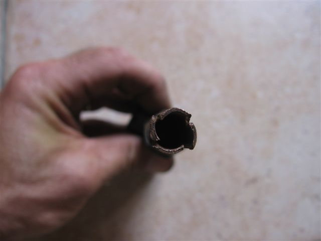
The realization gives this:

The orifices are respectively (from top to bottom): water - depression - air.
The end of the air tube ends with a AVEC, to facilitate the rotation of the air at the stem.
Stainless steel rod 180 mm used on the old assembly, has returned to lodge above the GV

View of the finished montage. The white pipe is the return of depression towards the trap

I tried the "last chance modification" proposed by Camel1, namely to use the vacuum in the air filter to balance the water level between the tank and the reactor
The two depressions are not identical and the water level rises, rises ... Until drowning the air supply.
Suddenly I got angry and I left - for now - the hollow stem. On the other hand, I am still trying to integrate the GV into the reactor base.
Here is a small diagram of principle:
The air always comes through the inner tube 8-10, the 12-14 used initially to convey the water now serves as a "stilling" tube (I don't know if that's the right word, but it sounds well). It senses the vacuum in the steam to balance the level in the trap.
The water now comes with a brass 15 / 21 bend, pierced to let 2 other concentric tubes.
The stilling tube also acts as a heat buffer (in yellow) between the warm air inlet and the boiling water. The temperature rise of the water should be faster than with the previous installation.
By extending the tube 8-10 I could have kept the principle of the hollow rod, but I did not have the courage. Immediately I want to validate my compact GV. If it works, it is a "space saving" solution that can be useful.
The realization gives this:
The orifices are respectively (from top to bottom): water - depression - air.
The end of the air tube ends with a AVEC, to facilitate the rotation of the air at the stem.
Stainless steel rod 180 mm used on the old assembly, has returned to lodge above the GV
View of the finished montage. The white pipe is the return of depression towards the trap
0 x
Hello
I think that as soon as you have more air than your depression you will not be able to suck the water through the reactor.
You should temporarily disconnect your water supply and connect a column of water instead.
You start the engine and measure the height of the water column at different speeds.
Your column should hardly move.
If it moves is that your depression is too important, so your air intake is too small.
I guess I'm not teaching you anything, anyway, that's how I would have done to control.
Good luck.
0 x
Hello,
And thank you Pitmix for all your ideas and suggestions.
3 different montages tested on 2 days:
1) My GV 3 hoses did not give the expected result: after 20 test km the car was still as sluggish.
I took a hot shower by removing the clamps to check the filling state of the hoses, all filled with water ... In short "there is water in the gas" ...
2) To compare the effect of an overpressure instead of depression, I reconnected the breather instead of the air intake, and re-test circuit on 20 km. To see the same thing.
At start-up it was better, but at the end of the test the air hose was so full of water that the breather gases were "blocked". No more steam flow to the engine.
Blowing into the air inlet pipe I spurted a shower of boiling water out of the reactor.
In short, this morning it was limited discouragement, especially since oil also always tends to come out of everywhere and that the platelets sometimes remain stuck to the discs: unpleasant screech and disruption of the conso ... What capricious!
Finally the initial assembly gave better results: the difference is that the steam entered the air filter through the small hole of the breather, while now it enters a manifold with venturi effect in the intake pipes. This significant increase in the depression was supposed to improve the operation of the reactor, but by raising the water level it gave the opposite effect ...
3) For now I found a montage that gives me almost the feelings that I originally had with my hollow stem. As Pitmix had suggested, I took the vacuum information not in the reactor, nor in the air filter, but directly on the reactor outlet pipe (or more exactly on the steam inlet at the filter to air).
The depression is therefore maximum at the level of the tank, and no longer the reactor. I just made 50 km like this and hope returns.
However I am still not sure if I have a "hang-up" of the reactor, it is possible that the engine is only running "on steam". in any case it does not hurt him.
The amount of steam observed seems weak, I will try to raise slightly the level of the tank.
There remains one unknown: for the moment, the inlet vacuum intake (the one placed between the water inlet and the air inlet) is in the open air, just closed by a cloth that serves vaguely as a filter, to avoid the engine swallowing too much junk.
Suddenly, if there is a rise in the level, too much water can escape there. The rag seemed damp to me, but I have not yet checked under the pit. If I can't find another solution, I will use this tube as too full, even if it means finding a way to recycle this "lost" water - but above all heated in pure waste.
It corresponds to my current test (3) the air enters at the same time by the inner tube (8-10) and by the taking of intermediate depression (12-14). If the level proves to be constant I can delete the inner tube and enter directly through the 12-14.
And better than a column of water, I found someone who can lend me a vacuometer.
_____
Yesterday I stumbled on a blog commentary, where an anonymous said to have passed under 3 l / 100 km on an AX 14D pantonée in 2005. It is plausible. Too bad I do not have his coordinates, it would have interested me.
How many are operating in a discreet way with a reactor, without sharing their feedback? It's too bad.
To be continued...
And thank you Pitmix for all your ideas and suggestions.
3 different montages tested on 2 days:
1) My GV 3 hoses did not give the expected result: after 20 test km the car was still as sluggish.
I took a hot shower by removing the clamps to check the filling state of the hoses, all filled with water ... In short "there is water in the gas" ...
2) To compare the effect of an overpressure instead of depression, I reconnected the breather instead of the air intake, and re-test circuit on 20 km. To see the same thing.
At start-up it was better, but at the end of the test the air hose was so full of water that the breather gases were "blocked". No more steam flow to the engine.
Blowing into the air inlet pipe I spurted a shower of boiling water out of the reactor.
In short, this morning it was limited discouragement, especially since oil also always tends to come out of everywhere
Finally the initial assembly gave better results: the difference is that the steam entered the air filter through the small hole of the breather, while now it enters a manifold with venturi effect in the intake pipes. This significant increase in the depression was supposed to improve the operation of the reactor, but by raising the water level it gave the opposite effect ...
3) For now I found a montage that gives me almost the feelings that I originally had with my hollow stem. As Pitmix had suggested, I took the vacuum information not in the reactor, nor in the air filter, but directly on the reactor outlet pipe (or more exactly on the steam inlet at the filter to air).
The depression is therefore maximum at the level of the tank, and no longer the reactor. I just made 50 km like this and hope returns.
However I am still not sure if I have a "hang-up" of the reactor, it is possible that the engine is only running "on steam". in any case it does not hurt him.
The amount of steam observed seems weak, I will try to raise slightly the level of the tank.
There remains one unknown: for the moment, the inlet vacuum intake (the one placed between the water inlet and the air inlet) is in the open air, just closed by a cloth that serves vaguely as a filter, to avoid the engine swallowing too much junk.
Suddenly, if there is a rise in the level, too much water can escape there. The rag seemed damp to me, but I have not yet checked under the pit. If I can't find another solution, I will use this tube as too full, even if it means finding a way to recycle this "lost" water - but above all heated in pure waste.
Pitmix wrote:I think that as soon as you have more air than your depression you will not be able to suck the water through the reactor.
It corresponds to my current test (3) the air enters at the same time by the inner tube (8-10) and by the taking of intermediate depression (12-14). If the level proves to be constant I can delete the inner tube and enter directly through the 12-14.
And better than a column of water, I found someone who can lend me a vacuometer.
_____
Yesterday I stumbled on a blog commentary, where an anonymous said to have passed under 3 l / 100 km on an AX 14D pantonée in 2005. It is plausible. Too bad I do not have his coordinates, it would have interested me.
How many are operating in a discreet way with a reactor, without sharing their feedback? It's too bad.
To be continued...
Last edited by crispus the 08 / 07 / 07, 13: 32, 1 edited once.
0 x

Hello Crispus
About your cloth that acts as an air filter. In my opinion it is plugged and not air filter. On a mob, one day I lost the air filter. Since I was doing motocross with, to preserve the engine I replaced the filter with a piece of cloth.
Result: Can not start and the engine drowned from drowned immediately. Back to normal as soon as I removed the sheet.
I did not understand everything in your diagram and I do not know if it is essential but in your place I would try with a real air filter.
A+
Crispus wrote:There remains one unknown: for the moment, the inlet vacuum intake (the one placed between the water inlet and the air inlet) is in the open air, just closed by a cloth that serves vaguely as a filter, to avoid the engine swallowing too much junk.
About your cloth that acts as an air filter. In my opinion it is plugged and not air filter. On a mob, one day I lost the air filter. Since I was doing motocross with, to preserve the engine I replaced the filter with a piece of cloth.
Result: Can not start and the engine drowned from drowned immediately. Back to normal as soon as I removed the sheet.
I did not understand everything in your diagram and I do not know if it is essential but in your place I would try with a real air filter.
A+
0 x
Reason is the madness of the strongest. The reason for the less strong it is madness.
[Eugène Ionesco]
http://www.editions-harmattan.fr/index. ... te&no=4132
[Eugène Ionesco]
http://www.editions-harmattan.fr/index. ... te&no=4132
Flytox wrote:I did not understand everything in your diagram and I do not know if it is essential but in your place I would try with a real air filter.
Hello Flytox,
It is true that this thread is long and that the photos are scattered ...
The cloth is used to plug the vacuum, originally intended to return to the tank level constant. The air inlet is distinct and has its filter (housed in the wing).
Question mob I had problems with a missing filter: the engine swallowed a grain of sand and I walked back. fortunately part of the way was in the right direction of the slope ...
To my father who smiled when he saw me push my bike, I go out "The shirt is striped". And he replies "It's fashionable"
0 x
Hello
An air filter to be effective and not too much resistance, must have a large area
for a reactor inlet a wax box or larger with a spinner foam, should suffice ..
Although often just for tests I put nothing, if it concludes I paufine these details, I roll only occasionally in gravel roads or beaten earth.
In the 50 years the cars did not even have an air filter, just a small hat over the carburetor, or engine oil filter .. at the beginning the air filters were silent
For your reactor to work, steam and air are needed at the reactor inlet (more air than steam).
Andre
About your cloth that acts as an air filter. In my opinion it is plugged and not air filter.
An air filter to be effective and not too much resistance, must have a large area
for a reactor inlet a wax box or larger with a spinner foam, should suffice ..
Although often just for tests I put nothing, if it concludes I paufine these details, I roll only occasionally in gravel roads or beaten earth.
In the 50 years the cars did not even have an air filter, just a small hat over the carburetor, or engine oil filter .. at the beginning the air filters were silent
For your reactor to work, steam and air are needed at the reactor inlet (more air than steam).
Andre
0 x
-
- Similar topics
- Replies
- views
- Last message
-
- 4 Replies
- 15970 views
-
Last message by Flytox
View the latest post
19/11/13, 22:03A subject posted in the forum : Water injection in engines: montages and experiments
-
- 3 Replies
- 9317 views
-
Last message by Flytox
View the latest post
08/12/10, 23:06A subject posted in the forum : Water injection in engines: montages and experiments
-
- 20 Replies
- 17240 views
-
Last message by rodibruno
View the latest post
04/05/09, 03:35A subject posted in the forum : Water injection in engines: montages and experiments
-
- 10 Replies
- 11741 views
-
Last message by ecolo
View the latest post
05/06/08, 23:02A subject posted in the forum : Water injection in engines: montages and experiments
-
- 27 Replies
- 22867 views
-
Last message by Other
View the latest post
10/03/08, 21:09A subject posted in the forum : Water injection in engines: montages and experiments
Back to "Water injection in the engines: the assembly and experimentation"
Who is online ?
Users browsing this forum : No registered users and 207 guests