GV on a tractor?

Edits and changes to engines, experiences, findings and ideas.
User avatar
Flytox
Moderator
Moderator
posts: 14141
Registration: 13/02/07, 22:38
Location: Bayonne
x 839

Re: Your reactions to a double-acting GVI


by Flytox » 21/02/10, 12:42

Hello Chantrel

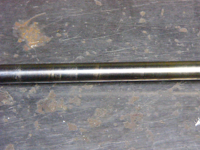
chantrel wrote:Here is a garden tractor carburetor, the air passes through a reverse of the normal pr that the venting is at the same depression as the GVI.

If I understood your montage correctly:
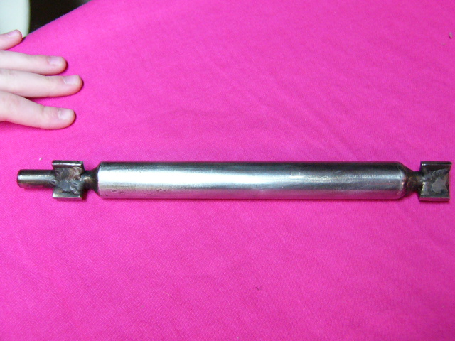
- you use the micro tractor fuel tank as a constant level, to supply the GVI.
- You regulate the air that enters your GV with the butterfly valve or bushel of fuel. At the same time it balances the upstream downstream pressure.
It's clever!
Small flat, the carbs are not made for water and it corrodes a maximum and does not work long (a week) before a whitish deposit bitch you and blocks everything (needle / float).

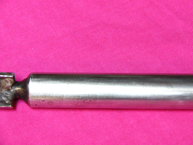
- How much is the diameter of the air passage of the fuel at the venturi?

The exhaust valve mounted on the GVI settled by weight, allows the opening are approximately de1400tr / min, warming and inside the GVI pr generate steam and preheat incoming air when the exhaust gasses are hotter for reactors.
From the engine idling, the gasses pass outside the GVI now in t °.

I don't quite understand what you want to do with this system.
Does that make you 2 different heating powers for your GV?
A+
0 x
Reason is the madness of the strongest. The reason for the less strong it is madness.
[Eugène Ionesco]
http://www.editions-harmattan.fr/index. ... te&no=4132
Chantrel
I discovered econologic
posts: 6
Registration: 19/11/09, 22:57
Location: brittany 35


by Chantrel » 22/02/10, 00:45

Hi Flytox,

the venturi of my carburetor is 22mm (too big compared to the air duct, you need a restriction to have a slight depression.
But the problem is to find a constant reliable level ...
Because no way the engine swallows a drop of water if the constant level leaks ... :?

Unless fixed at the right height compared to the GVI a mini water tank with float in the open air (like a HP cleaner), like that if the float leaks, the water flows outside. : Lol:

Of course, all tips are welcome!

My valve system?
This is to produce steam + hot air from a desired engine speed.
ex. : the valve opens at about 1600 rpm, the reactor (s) are at temperature for "operated" the entry of the mixture which is created in the GVI.

See doc. attached
a+


Image
0 x
User avatar
Flytox
Moderator
Moderator
posts: 14141
Registration: 13/02/07, 22:38
Location: Bayonne
x 839


by Flytox » 27/02/10, 00:05

That you put settings, valves etc ... it's good in the sense that you can explore lots of different configurations and that there are a lot of ways to clear. On the other hand, a big engine like yours, shouldn't have any worries to produce steam at slow speed and therefore reduce its pollution if you want to make it ingest. :P

You will not make differences in consumption at low speed but on the other hand for pollution, smoke etc ... you have an immediate gain.
A+
0 x
Reason is the madness of the strongest. The reason for the less strong it is madness.

[Eugène Ionesco]

http://www.editions-harmattan.fr/index. ... te&no=4132
User avatar
coucou789456
Grand Econologue
Grand Econologue
posts: 1019
Registration: 22/08/08, 05:15
Location: Narbonne


by coucou789456 » 27/02/10, 05:10

Good evening

chantrel wrote:Well, then there must be a beginning of everything! I'll test this GVI.

I had seen an article of an experimenter (or I do not know, I search) that he noticed that the moist air entering the reactor began to rotate around the rod when it is directed towards northern terrestrial pole and normally flowed towards the south pole.

..............


in fact the turbulence induced in the reactor causes the air / vapor mixture to rotate around the rod with a pitch equivalent approximately to the diameter of said rod.
this phenomenon induces a more or less intense magnetic field in the rod and the whole reactor of course, but on the other hand it does not seem that there is a notable influence on the overall functioning of the system, although no study to my knowledge n was done in this direction, to determine an impact on the actual operation.

on the other hand, the cavity located at the end of the reactor, as well as the shape of the end of the rod is important. it is in this cavity that the "transformation" of the air / vapor mixture so dear to gillier pantone must take place.
there must be a transformation because otherwise a simple production of hot steam would be enough to produce the same effects.

a sufficiently long reactor is therefore needed for turbulence to be produced at low engine speeds, a particular shape of the end of the rod (shell shape). by virtue of the turbulence produced, the resulting magnetic field must greatly assist the "transformation". this famous magnetic field is a result of the operation but it must take place an ionization of the mixture at the end of the rod, never demonstrate because no one has gone to see it.

the fact is that a good, careful implementation produces the expected effects, ie a very noticeable reduction in pollution, and fuel consumption, which even if this results in a reduction in power, for the same engine, the manufacturer doesn 'does not indicate such low fuel consumption.

jeff
0 x
User avatar
Flytox
Moderator
Moderator
posts: 14141
Registration: 13/02/07, 22:38
Location: Bayonne
x 839


by Flytox » 27/02/10, 13:37

Hello coucou789456

coucou789456 wrote:in fact the turbulence induced in the reactor causes the air / vapor mixture to rotate around the rod with a pitch equivalent approximately to the diameter of said rod.


It is not systematic, the traces of deposit found on the rods of my assembly have never left traces in a spiral. On the other hand, André spoke of these spiral traces .... but which could also have been traces caused by the wrought during the manufacture of the rod.

For test, I wrapped a spring around the lower part of the rod so as to force the vapor to turn between the turns and therefore to turn around the rod. It didn't bring anything more ....

Do you have results of experiments on the influence of the end of the rod (shell shape etc ...)?
A+
0 x
Reason is the madness of the strongest. The reason for the less strong it is madness.

[Eugène Ionesco]

http://www.editions-harmattan.fr/index. ... te&no=4132
User avatar
coucou789456
Grand Econologue
Grand Econologue
posts: 1019
Registration: 22/08/08, 05:15
Location: Narbonne


by coucou789456 » 27/02/10, 14:13

Hello

Posted on: Wed 11 Oct 2006, 00:28 Post subject: Unifying theory: Pantone, Vortex and planet Earth

and posted by André

Quote:
the coil marks on the rod were identified by christophe as being the result of the machining of the rod (rod made on a lathe)

Practically impossible that these traces come from a lathe, all those who have manipulated a lathe will be able to confirm it it would be necessary to make a big advance on the carriage to make a propeller which far exceeds the pitch known threads, Normally in the manufacturing process of these rods it does not pass on a lathe, but in a grinding machine, for polished machined rods.
The posibility is a straightening operation with 3 angle rollers that we use in the industry for precision round rods, in some cases I took the trouble to polish the rod with sandpaper, but we can not say beyond all doubt that these marks do not come from a rectifier by a local hardening which would resort to heat? One thing is sure, the pitch of this spiral always corresponds to the radius of the rod
whether in steel or stainless steel and the direction of rotation is always the same.


here are the traces on the stem. by reading this reminder, you will have corrected the error that I made by indicating a step equal to the diameter of the rod while it is equal to the radius of the rod.

for the rest I seek my sources.

jeff
0 x
User avatar
coucou789456
Grand Econologue
Grand Econologue
posts: 1019
Registration: 22/08/08, 05:15
Location: Narbonne


by coucou789456 » 27/02/10, 15:03

Hello again

posted by André on Fri 04 Nov 2005, 21:57 subject: Renault Super 5 doped with water

You're well gone, your reactor is well positioned, for the stem it is not necessary to make an aerodynamic shape for the entrance, even a square cut works slightly better, for the output of rod is correct in tip.


jeff
0 x
Other
Pantone engine Researcher
posts: 3787
Registration: 17/03/05, 02:35
x 12


by Other » 27/02/10, 20:24

Hello

I stopped looking for the why of the spiral, after looking for ways to force it, which did not improve the system.
I ended up concentrating on the steam entering the reactor, it was only at this place that I managed to have improvements.

Although once reaching 33% it becomes difficult to increase these values ​​and the tests become random, it takes long tests with a quantity of measures of notes and against verification.
It is preferable to concentrate this at 25% continuously on all diets and more particularly to improve city driving.

Small advice makes a simple assembly, easily versatile, at least for what is around the reactor, do not seek a complex regulation which will give you more trouble to develop, rather seeks to balance the assembly around the usual regimes of the tractor, and forget slow motion and very low power, you will burn your character, and ultimately give up.

Andre

Local cavitation on an inconel rod

Image


some hairspring on a 12,7mm steel rod and small pin
Image


Rod which was passed to the sandpaper one sees slightly the spiral

img] https://www.econologie.com/fichiers/partager2/1267298522Q7PQvr.jpg [/ img]

19mm rod in stainless steel water doping of 300D
Image


Image
0 x

Back to "Water injection in the engines: the assembly and experimentation"

Who is online ?

Users browsing this forum : No registered users and 140 guests