Put a picture of my GV, it may help you ...
https://www.econologie.com/fichiers/partager/DSCN3391.JPG
And a small one of the "holed" exhaust ...
https://www.econologie.com/fichiers/partager/DSCN3398.JPG
Olivier
GVI process on BMW 318 tds
Hello
You know if you thought about it too, is that the idea is good
remember though if i put it on the forum it is so that others do the same. I also take ideas on the forum that's what the forum..
For the internal duct even if it was long the rod can make that 200mm to 300mm it can be positioned in the hottest place (common exit towards the turbo)
For the control of the steam flow Michel on his site made a detailed explanation with the physical dimensions according to the engine power or the load (the bigger the exchanger the more the production of steam is important)
although there must be a way to control the flow of steam entering the reactor, normally the entry of auxiliary air influences the steam passing through the reactor.
almost all of us have a problem how to control the steam flow with bubblers or steam generators
Zac does not have this problem it changes the nozzle either, but the fact remains that it takes a lot of hard work to find the right values.
Andre
.....As for the idea of centering with the cap, you swear it's not copying, I thought about how to center it well and know how to get it out easily
You know if you thought about it too, is that the idea is good
remember though if i put it on the forum it is so that others do the same. I also take ideas on the forum that's what the forum..
For the internal duct even if it was long the rod can make that 200mm to 300mm it can be positioned in the hottest place (common exit towards the turbo)
For the control of the steam flow Michel on his site made a detailed explanation with the physical dimensions according to the engine power or the load (the bigger the exchanger the more the production of steam is important)
although there must be a way to control the flow of steam entering the reactor, normally the entry of auxiliary air influences the steam passing through the reactor.
almost all of us have a problem how to control the steam flow with bubblers or steam generators
Zac does not have this problem it changes the nozzle either, but the fact remains that it takes a lot of hard work to find the right values.
Andre
0 x
So, if I'm your resonance, even if I put a 35cm tube and the central rod is only 10cm, as long as it is opposite the outlet to the turbo it would work ???
I ask you that because I have an idea that bothers my mind for this mounting in a 6-cylinder so even longer exhaust and which I will share with you very soon (Christophe is already aware).
I ask you that because I have an idea that bothers my mind for this mounting in a 6-cylinder so even longer exhaust and which I will share with you very soon (Christophe is already aware).
0 x

roulez123 wrote:So, if I'm your resonance, even if I put a 35cm tube and the central rod is only 10cm, as long as it is opposite the outlet to the turbo it would work ???
Hello
below 120 / 130mm I have never been able to operate a pantone, on the other hand at 250/300 I have never seen any gain compared to a 150mm core.
So I make rods from 130 to 200 depending on the easiest to mount
@+
0 x
Said the zebra, freeman (endangered breed)
This is not because I am con I try not to do smart things.
This is not because I am con I try not to do smart things.
hi Zac
Very interesting your analysis.
If you have never managed to operate a Pantone with a 120 / 130mm rod it is that without a rod it should not work either.
For my part by measuring the steam outlet temperatures, without rod I noticed that the reactor drowns very quickly.
In other words with rod I balance 1L / 100km of floats and the temperature remains correct at + 100 ° C while without rod it goes down to 50 ° C even with 0,3L / 100km of water.
I had to send a flow of 0,2L / 100km and intermittently 3sec.
The air / water ratio in the reactor is greatly modified which poses a problem.
The best way to avoid this concern is to transform directly into the reactor GV rather than using it with too small rod or even without stem.
Finally this is my opinion from what I have observed.
0 x

Hello,
It is also my opinion, this is what I'm currently testing since 2 weeks on my AX diesel. I counted expect concrete results, but Pitmix kindly teased about it
So preview:
I prepare a report as complete as possible on the assembly and testing in progress (300 km from the latest development), with a bonus balance with pollution soon courtesy of Matmatdumdum.
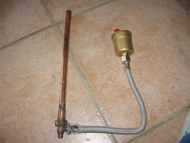
And looks like this installation:
PITMIX wrote:The best way to avoid this concern is to transform directly into the reactor GV rather than using it with too small rod or even without stem.
Finally this is my opinion from what I have observed.
It is also my opinion, this is what I'm currently testing since 2 weeks on my AX diesel. I counted expect concrete results, but Pitmix kindly teased about it
So preview:
I prepare a report as complete as possible on the assembly and testing in progress (300 km from the latest development), with a bonus balance with pollution soon courtesy of Matmatdumdum.
And looks like this installation:
0 x
Hello Crispus
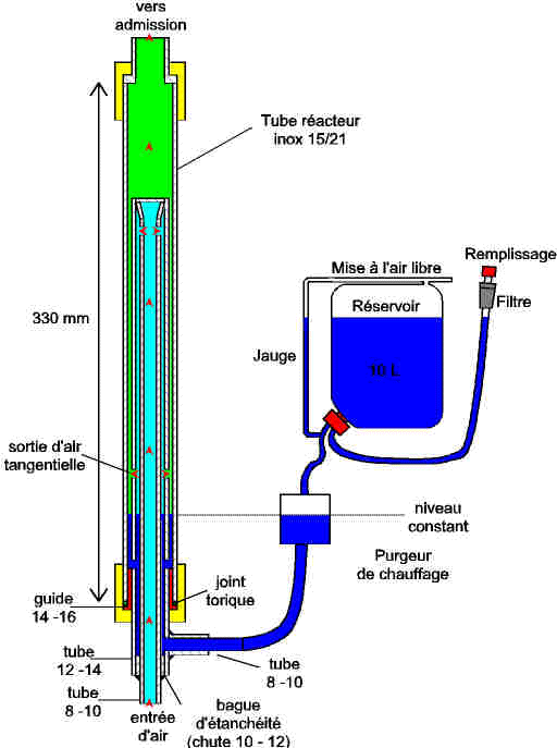
The point that intrigues me is the body of the tubular rector copper
In my early try on comparisons with differrent materials, aluminum, steel, stainless steel, it is with the copper that I had the worst results, but it was a 100% panton mounting works on fuel oil on an engine a blast.
It may be quite different in doping water ..
As for the GV copper it is a material that exchanges heat well, so it should work well.
just watch the position of the small steam outlet holes with the water level, it takes a vertical system.
Keep us informed of positive or negative results. It is always interesting to know if this or that material makes a difference, however small it may be.
It is also interesting to make the comparison between a solid rod and a hollow rod with thin walls. (That I tried it)
Also make the comparison to a rodless (exchanger), to know if simply a dose of vapor mixed with air what yield it gives.
At the end, a bundle of small stainless steel tubes with an internal diameter of 2 mm would not do the same thing as a reactor.
Andre
0 x
Andre wrote:The point that intrigues me is the body of the tubular rector copper
In my early try on comparisons with differrent materials, aluminum, steel, stainless steel, it is with the copper that I had the worst results, but it was a 100% panton mounting works on fuel oil on an engine a blast.
It may be quite different in doping water ..
Hi to you, Andre, model experimenter.
This assembly is "like that" because I could not do otherwise ...
- Copper is all I had on hand, otherwise I would have made of stainless steel.
- My vertical reactor ends below the exhaust, so not possible to install a steam generator below.
I had a good idea in mind since 3 months, but difficult to express.
The original idea was that "everything can fit", because on my tank the ingenious Citroën used all the space available under the hood to house the engine and its accessories.
- No room for a bubbler, I even had to put the water tank under the dashboard like a "passenger waterbag".
- No carbs on hand and a certain reluctance to use this machine of which I still cannot understand the subtleties ... I nevertheless followed the reference work "the pages of Mr. David" but there I blocked...
Then I thought of using the bottom of the reactor bubbler. But I know from experience that a mini bubbler causes liquid water and not steam. Hence the idea (quilted ...? On post No.?) Of the hollow rod.
And I remain convinced that my theory is not (completely) wrong:
- The swirling gases is essential for proper operation,
- The performance will be better if the tourbillon reached each cylinder (coupling WITH a vortex)

- Steam must be and remain at a low temperature for a good ionization
My idea is that:
- If the installation is operational, the reactor end temperature drop should maintain just enough to allow boiling (50 °?)
- The intake air from the breather, circulating in the stem will prevent heat under the effect of: cavitation - the arc - other? (delete as appropriate)
In my humble opinion, the copper rod is malfunctioning because it leads so the heat it heats the incoming steam to the point of him exceed 100 ° C, or loss of ionization.
Here my bet is that the reactor outlet gas will remain at a low temperature, but strongly ionized and with a great angular velocity (see my theory which makes "seasoned" thermodynamicists cringe - citroën obliges;))
0 x
PITMIX wrote:Wow !!!
So say ... it's great art ...
As much for the quality of the diagrams as for the ideas of designs. I would say only one word BRAVO
It remains to be seen what happens ...
Thank you Pitmix, but my charentaises do not support shoe polish
This is what happens once the engine is warm (checked after 4 kilometers in town, I did not think of stopping before):

I will put a flat, because the air comes from the breather and I still do not know the amount of steam added by the GV). in any case it seems to me to work better and better over the km.
Well, in order not to pollute this post, I will soon open another one with what I already have on hand.
... See you soon, I hope !
0 x
-
- Similar topics
- Replies
- views
- Last message
-
- 160 Replies
- 78421 views
-
Last message by Flytox
View the latest post
21/04/10, 22:55A subject posted in the forum : Water injection in engines: montages and experiments
Back to "Water injection in the engines: the assembly and experimentation"
Who is online ?
Users browsing this forum : No registered users and 143 guests