Yes André if I had to put the water carburetor as on the modified photo, the water tube would also be fixed against the exhaust just to be heated.
The problem is that for the photo I took the old reactor of the R5 so it's just to illustrate my assembly.
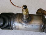
In reality there is not the steel elbow but a copper elbow and everything is welded. I cannot interlock my water fuel.
The thing I could do is peck with a very thin little tube of water with the pipe against the exhaust.
Camel1 yes I saw that on your site.
In fact at the beginning of my experiences I used an exchanger on the coolant in my car.
It was identical to yours except that it was already ready.
It is an exchanger for the cold room fridge circuits at the base.
According to your calculation my GV should be 240 / 1,9L = 126,32mm
GOLF 3 1,9D: Water doping
Hello
I reassembled the reactor like the last version, that is to say with the injection of water by windshield washer pump and nozzle.
I pass the breather through the reactor and I notice again that the smell of exhaust has disappeared.
With the reactor used in HS as in my photos it should not go since the odor was present. Technical control also proves that it was wrong.
It does not prove that the GV alone does not give a reduction in pollution but it proves that my GV did not work well.
At least from what my nose smelled .
.
Too bad I may have had to get the car to control in this configuration.
I reassembled the reactor like the last version, that is to say with the injection of water by windshield washer pump and nozzle.
I pass the breather through the reactor and I notice again that the smell of exhaust has disappeared.
With the reactor used in HS as in my photos it should not go since the odor was present. Technical control also proves that it was wrong.
It does not prove that the GV alone does not give a reduction in pollution but it proves that my GV did not work well.
At least from what my nose smelled
Too bad I may have had to get the car to control in this configuration.
0 x
Hello Pit
One of my first montages on the chevrolet that you have seen on the forum pmc
it is very close to a GV c, is a water tanker which spits in an envelope at the end of the reactor if your memories are good Pit these photos were on the other forum but because of the frost in winter I changed the way of doing it I have additional problems that you do not have .. the cold for 5 months ..
Andre
0 x
Yes André I know these photos well it is besides the assembly which I wanted to make on the R5 at the beginning , but I did not understand from the start that there was a double wall around the exhaust before entering the reactor.
I wanted to redo the same kind of assembly on the Golf but simpler by putting a tube welded against the exhaust in order to preheat the water before entering the reactor but then again I think that it is not enough. More volume was needed to let the steam dissipate.
By cons I am not 100% sure that it does not work.
I do not feel a performance enhancing effect but I still have the impression that something is happening.
If the disappearance of the smell of the exhaust is a precursor, then I can continue in this direction.
I will try to make a GV like Michel and Didier but I don't want to cut my exhaust.
I don't have enough arc welding experience to close the hole properly.
0 x
Hi everyone 
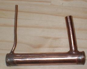
I made a small Camel1-style GVI.
I don't know yet if I'm going to install it on the Golf because what makes me sweat is to close the exhaust after having opened it Cesarean way.
In addition there is not much room left between the reactor and the "intermediate silencer" (or catalyst ?? !!).
GVI Test Video
Last edited by PITMIX the 21 / 03 / 07, 19: 35, 1 edited once.
0 x

Hello Pitmix,
I do not know if it may interest you, I submit my idea to you before you intervene on your escape.
I thought about the GV by re-reading the tests of Camel1. His idea is very good because it allows you to have steam very quickly.
On the other hand I find that it would be necessary to be able to limit the temperature of the vapor to around 90 ° C. to conserve its ionization, as is done with a bubbler with coolant.
Hence this schematic diagram:

The idea is to divert part of the exhaust flow with a flap when the heat exceeds a certain threshold.
I have shown a thermostatic diesel accelerator downstream of the GV, but it must tilt around 60 ° C, it's too fair.
Suddenly I wonder if the top would not be to divert the original EGR valve by controlling it by a thermostat?
Another difficulty: ensure the tightness of the system, ie preferably find a mechanism that can remain internal to the pipe, because high temperature joints are not given ...
I drew the GV in the added tube because it seems easier to manage: we can imagine a removable connector rather than welded, in order to intervene on the shutter for example ...
I do not know if it may interest you, I submit my idea to you before you intervene on your escape.
I thought about the GV by re-reading the tests of Camel1. His idea is very good because it allows you to have steam very quickly.
On the other hand I find that it would be necessary to be able to limit the temperature of the vapor to around 90 ° C. to conserve its ionization, as is done with a bubbler with coolant.
Hence this schematic diagram:
The idea is to divert part of the exhaust flow with a flap when the heat exceeds a certain threshold.
I have shown a thermostatic diesel accelerator downstream of the GV, but it must tilt around 60 ° C, it's too fair.
Suddenly I wonder if the top would not be to divert the original EGR valve by controlling it by a thermostat?
Another difficulty: ensure the tightness of the system, ie preferably find a mechanism that can remain internal to the pipe, because high temperature joints are not given ...
I drew the GV in the added tube because it seems easier to manage: we can imagine a removable connector rather than welded, in order to intervene on the shutter for example ...
0 x
-
laurent.delaon
- I understand econologic

- posts: 168
- Registration: 13/08/05, 17:49
Hello ,
you made a mounting error: the inlet tube must be at the bottom (or turned a quarter) and not in the direction of that of the outlet otherwise it will not work very smart ...
I point out to you the fragility of this assembly which will break fairly quickly (after about 4000km (even if it is not easy to read in the crystal ball but after all there are some who find remarkable physical properties in the Pantone reactor, so ... )
You are right to do this without the scrap of iron (commonly known as the Pantone Reactor).
0 x
Hi Laurent
Did you watch the video?
Isn't that what you call walking?
You simply need an elbow facing upwards at the steam outlet. Compared to the test on the video, the tubes are normally horizontal.
If I made the two tubes like that it is because there is a good reason. The bulk of the room does not allow me to do what I want on my car. The more the reactor it makes the world.
But anyway it is not bad even if it is not good since I will not mount this thing in my exhaust.
It allowed me to do bench tests.
I even put my exhaust also on the workbench to make life-size tests with the reactor used in HS.
I noticed that by placing the float at the bottom of my reactor I get good steam but the level is difficult to adjust.
Little difference between minimum and maximum. Ditto on the GVI in copper elsewhere.
I tried by placing the float at the reactor outlet as I had done previously. Here it is even worse. There is too easily water coming out of the steam tube and the right level is almost impossible to find. The steam is weak.
I finally put the float on the inlet of the reactor (copper tube against the exhaust).
There I get the same thing as with the float at the bottom of the reactor.
Good steam and low water level but not impossible to find.
Finally I put everything back on the car and with my little syringe and the windshield washer pump I can get the same thing better.
This is the big smart guy finished his spitch
0 x
-
camel1

- Pantone engine Researcher

- posts: 322
- Registration: 29/01/05, 00:29
- Location: Loire
- x 1
- Contact :
Hi Pit!
I missed an episode, so I'm catching up!
Your achievement seems good to me, and you stumble on the bp of the implementation of GV in the line.
Given the mouth of your exhaust line, the ideal place would be in the kind of silencer, by positioning the GV on a slope (to have the bottom that bathes ...)
With the reactor just above, alignment would be ideal.
As for the dimension, it seems to me consistent with what we did, it should work nickel ...
It remains to ask, and there, indeed, it would be necessary to make a surgical operation, and, it seems, that you find a friend welder able to do it ...
However, given your config., I think you could be inspired by the stuff that we used for the mercury, and that I did not explain too much on the site. Look at the 8th photo from the top there:
http://reaction.directe1.free.fr/Merco220D/merco.htm
You can see the GV at the end of the exhaust tube, we did not open the tube as on the 205, but just located the location of the water inlet (bottom) and the steam outlet ( up).
Drilling 4,5 mm for the small hole, and 12,5 for the large one.
It is necessary to "work" the small hole with an old drill (or a piece of scrap of 4 mm) in inclination towards the back (in the direction of the GE) to soften the entry of the feeding tube.
Then prepare the GV with a good length of tube 4 mm (like 20 cm) and the steam outlet tube of a length allowing the assembly to enter the exhaust tube.
In my case, the size of the steam outlet and the exchanger was: 50 mm inside diameter of the sample tube. minus 22 mm from the GV equals 28 mm (a little less in reality)
It is best to adjust the correct length of the steam outlet AFTER brazing it.
Once done, put the tube of 4 straight, with a small curve at the end, then engage it so as to bring out the end through the small hole of 4,5 ...
You can make your life easier by using a needle like in electricity (and in plumbing, for that matter).
You push in the GV by pulling the tube of 4, until the steam outlet tube is in front of the hole, then you engage it in and brings it out outside until you have a good centering of your GV (the tubes must be concentric!)
And there, you just have to braze the two tubes at the level of the small holes, with a tube sleeved and possibly bent on the steam outlet (the end which leaves the sample tube will not be long enough).
I detail this manufacturing, because I think you could approach this method by cutting the tube at the outlet of the pot (reactor side).
Like me, you make a big hole at the top, just before flaring the pot, and a small one at the bottom of the pot, where it suits you.
You can then install your GV as on the merco, and you just have to arc weld the reactor tube, knowing that at the flange (where you cut), the metal is thicker , and it greatly facilitates welding ... nothing to do with the sheet metal of the tube! 
And above all, it makes for a lot less baguette to cram!
Remember to make the overflow hole at the top of the tank, and if possible, provide a temperature probe on the steam hose, as close to the reactor inlet, it is a good guide to know if the sizing is good (and that will give us feedback to possibly refine the formula ... )
To answer the passage to Crispus, I find his idea very interesting, I had thought of the rest of a system of this kind ...
However, by design, we sought to have a GV which gives good fork temperatures (between 40 and 98 ° C), whatever the conditions, the factor driving the regulation being the speed and the heat of the GE, that is to say, as a last resort, the intensity and the liveliness of the engine calls ...
It is actually designed to achieve the simplest possible control loop.
Hence the importance of the exchange surface, which is decisive at the level of the maximum temperature.
The other determining factor for this maximum temperature is the value of the maximum vacuum, because it influences the boiling point of water.
I think that the formula will have to evolve on this point there, by adding a factor in 1 / P, we will see later ...
To summarize, even if two simple nested tubes may seem trivial, the fact remains that the question of their dimensions and their implementation is not that obvious (and yes Laurent )
In any case, if you do as I explained to you, you should have results for sure.
Oh yes, by the way, in terms of reliability, and contrary to what Laurent asserts, there is no break after 4000 km, just provide a curve on the 4 mm tube, which can take the expansion differentials, and voila!
The GV of my 205 at 15 km, and still works nickel!
Good luck Pit, and see you soon!
PS. Normally, I give the results of the vibration analysis bench this week ... stay tuned!
I missed an episode, so I'm catching up!
Your achievement seems good to me, and you stumble on the bp of the implementation of GV in the line.
Given the mouth of your exhaust line, the ideal place would be in the kind of silencer, by positioning the GV on a slope (to have the bottom that bathes ...)
With the reactor just above, alignment would be ideal.
As for the dimension, it seems to me consistent with what we did, it should work nickel ...
It remains to ask, and there, indeed, it would be necessary to make a surgical operation, and, it seems, that you find a friend welder able to do it ...
However, given your config., I think you could be inspired by the stuff that we used for the mercury, and that I did not explain too much on the site. Look at the 8th photo from the top there:
http://reaction.directe1.free.fr/Merco220D/merco.htm
You can see the GV at the end of the exhaust tube, we did not open the tube as on the 205, but just located the location of the water inlet (bottom) and the steam outlet ( up).
Drilling 4,5 mm for the small hole, and 12,5 for the large one.
It is necessary to "work" the small hole with an old drill (or a piece of scrap of 4 mm) in inclination towards the back (in the direction of the GE) to soften the entry of the feeding tube.
Then prepare the GV with a good length of tube 4 mm (like 20 cm) and the steam outlet tube of a length allowing the assembly to enter the exhaust tube.
In my case, the size of the steam outlet and the exchanger was: 50 mm inside diameter of the sample tube. minus 22 mm from the GV equals 28 mm (a little less in reality)
It is best to adjust the correct length of the steam outlet AFTER brazing it.
Once done, put the tube of 4 straight, with a small curve at the end, then engage it so as to bring out the end through the small hole of 4,5 ...
You can make your life easier by using a needle like in electricity (and in plumbing, for that matter).
You push in the GV by pulling the tube of 4, until the steam outlet tube is in front of the hole, then you engage it in and brings it out outside until you have a good centering of your GV (the tubes must be concentric!)
And there, you just have to braze the two tubes at the level of the small holes, with a tube sleeved and possibly bent on the steam outlet (the end which leaves the sample tube will not be long enough).
I detail this manufacturing, because I think you could approach this method by cutting the tube at the outlet of the pot (reactor side).
Like me, you make a big hole at the top, just before flaring the pot, and a small one at the bottom of the pot, where it suits you.
You can then install your GV as on the merco, and you just have to arc weld the reactor tube, knowing that at the flange (where you cut), the metal is thicker , and it greatly facilitates welding ... nothing to do with the sheet metal of the tube!
And above all, it makes for a lot less baguette to cram!
Remember to make the overflow hole at the top of the tank, and if possible, provide a temperature probe on the steam hose, as close to the reactor inlet, it is a good guide to know if the sizing is good (and that will give us feedback to possibly refine the formula ...
To answer the passage to Crispus, I find his idea very interesting, I had thought of the rest of a system of this kind ...
However, by design, we sought to have a GV which gives good fork temperatures (between 40 and 98 ° C), whatever the conditions, the factor driving the regulation being the speed and the heat of the GE, that is to say, as a last resort, the intensity and the liveliness of the engine calls ...
It is actually designed to achieve the simplest possible control loop.
Hence the importance of the exchange surface, which is decisive at the level of the maximum temperature.
The other determining factor for this maximum temperature is the value of the maximum vacuum, because it influences the boiling point of water.
I think that the formula will have to evolve on this point there, by adding a factor in 1 / P, we will see later ...
To summarize, even if two simple nested tubes may seem trivial, the fact remains that the question of their dimensions and their implementation is not that obvious (and yes Laurent
In any case, if you do as I explained to you, you should have results for sure.
Oh yes, by the way, in terms of reliability, and contrary to what Laurent asserts, there is no break after 4000 km, just provide a curve on the 4 mm tube, which can take the expansion differentials, and voila!
The GV of my 205 at 15 km, and still works nickel!
Good luck Pit, and see you soon!
PS. Normally, I give the results of the vibration analysis bench this week ... stay tuned!
0 x
We were on the brink, but we made a big step forward ...
-
rezut

- I understand econologic
- posts: 191
- Registration: 01/12/04, 14:58
- Location: Chalon sur Saone
- x 2
Hi pit and hello everyone
taken speed by camel I was going to offer you the same solution but since it is he who realized it was faster than me
for me the pantone is over (on the bx) she rests before the son has the permit
But I still have a pantone on the 2cv that I am finishing to restore
Even if I do not participate I am always from time to time
Good luck Pit, and see you soon!
I don't know yet if I'm going to install it on the Golf because what makes me sweat is to close the exhaust after having opened it Cesarean way.
taken speed by camel I was going to offer you the same solution but since it is he who realized it was faster than me
for me the pantone is over (on the bx) she rests before the son has the permit
But I still have a pantone on the 2cv that I am finishing to restore
Even if I do not participate I am always from time to time
Good luck Pit, and see you soon!
0 x
-
- Similar topics
- Replies
- views
- Last message
-
- 7 Replies
- 12517 views
-
Last message by Chemsou
View the latest post
13/05/09, 18:30A subject posted in the forum : Water injection in engines: montages and experiments
-
- 6 Replies
- 10198 views
-
Last message by stepydan
View the latest post
22/09/07, 18:56A subject posted in the forum : Water injection in engines: montages and experiments
-
- 11 Replies
- 15338 views
-
Last message by PITMIX
View the latest post
16/02/07, 21:04A subject posted in the forum : Water injection in engines: montages and experiments
Back to "Water injection in the engines: the assembly and experimentation"
Who is online ?
Users browsing this forum : No registered users and 126 guests