Doping 508d steamed with a RETROKIT: NO RESULTS

Edits and changes to engines, experiences, findings and ideas.
jime
Éconologue good!
Éconologue good!
posts: 215
Registration: 25/01/08, 18:53
Location: Var - Ardeche

Doping 508d steamed with a RETROKIT: NO RESULTS


by jime » 25/01/08, 19:11

Hi all, I'm yours forum for some time now, especially the sections and articles concerning water doping processes. So I could see the fixtures on the 300td mercedes or the 205 diesel.

I was also able to read some controversies around the systems for sale or around patents.

So I specify that I am a lambda client, I am not the one for the controversy or to advertise, I am here to share my experience and evolve this system by finding possible changes.

So I do not know if you've already guessed but I bought a retrokit, the E1-45 engine up to 100cv, by correspondence to the Hypnow store.

I installed one on 508d 1985 mercedes, low pressure direct injection, 3L8 engine, 80CV, 13L / 100km cons, I roll to 10 to 30% HVB winter-summer

Here are the pictures of the montage

The bubbler: I realized it according to the plans given on the hypnow site


: Shock: : Shock: 8mars: this bubbler is obsolete because inefficient, the bubbling water does not rise sufficiently in temperature, for the moment I experiment a steel, see further in the subject

: Shock: : Shock: edit the 06 may, the retrokit is as effective as the PVC bubbler, I also deleted it,DO NOT BUY, build yourself your reactor, this company, Hypnow, sells an unfinished product that produces no results, these are only marketing ace


Image

The bubbler with its 4L water tank and 12V pump

Image
Last edited by jime the 06 / 05 / 08, 08: 52, 5 edited once.
0 x
jime
Éconologue good!
Éconologue good!
posts: 215
Registration: 25/01/08, 18:53
Location: Var - Ardeche


by jime » 25/01/08, 19:18

The retrokit
The water arrives through the entrance on the left through the retrokit and comes out right

Image

Drilling on a tube of 50mm

Image

Installation with the joint paste for exhaust and 2 serflex, if it leaks I would weld ..

Image

inside view, exhaust line start, exhaust manifold

Image

setting up the exhaust line

Image

1- start bypass heating hose outlet before the shut-off valve heater
2- return bypass heating hose after crossing the bubbler
3- arrival of the mixture in the air intake

Image

the bubbler, the hose is the bypass of the heating circuit, the copper is the water flow to the reactor

Image

seen from below, the copper of the bottom is the departure towards the admission of air, the copper of the top is the arrival of water since the bubbler
Image
0 x
jime
Éconologue good!
Éconologue good!
posts: 215
Registration: 25/01/08, 18:53
Location: Var - Ardeche


by jime » 25/01/08, 19:19

Some details

before putting the serflex, I worked the piece with the hammer so that it fits the shape of the exhaust pipe

Image

when you see the mouth of the weld (which does not leak!) you understand why I test the serflex before soldering

Image

brass fitting MM 15 / 21-13 / 17, sealing of the thread at the exhaust pipe

Image

an overview, everything goes under the bonnet without jamming the accelerator zipper
I may replace the hoses that affect the cylinder head with copper

Image
0 x
jime
Éconologue good!
Éconologue good!
posts: 215
Registration: 25/01/08, 18:53
Location: Var - Ardeche


by jime » 25/01/08, 19:20

New edit 2 days later

after a few modifications, I lowered the 15 bubbler approximately cm, I shortened the feed pipe and changed the inlet and outlet hoses, I switched from 12 * 14 to 8 * 10 and close the intake of gas mixture to the motor to have more suction in the bubbler

result: it bubble, I have suction in the air inlet of the bubbler, we feel the depression by clogging with the finger

no problem with the derivation of the heating hose, it rises quickly in temperature and warms the bubbler with closed heating

Image

1- stitching at the engine inlet, I have silicone for sealing
2- lower bubbler, shorter copper pipe, 80-90cm
3- at the bottom of the bubbler, I put an 16 copper angled to prevent the hose pinch with the angle 180 °
4- direct heating hose without elbow and without touching the cylinder head
0 x
jime
Éconologue good!
Éconologue good!
posts: 215
Registration: 25/01/08, 18:53
Location: Var - Ardeche


by jime » 25/01/08, 19:21

The end of editing today

Successful test phase: the system works, I have water droplets that arrive at the air intake

1- the switch that triggers the pump to fill the bubbler
2- a piece of transparent hose to control the smooth running
Image

bottom view of the bubbler, taken towards looking forward
Image

the 4L tank, the garden hose is the overflow of the bubbler and the water flow of water to the bubbler is the transparent 6mm hose
fixed with a strap to be removable easily, I refuel from the top with a hose extension
Image

the hose stopped, there is condensation, I had just used the system
Image

while traveling at about 80km / h
Image

always rolling
Image

The same video, it's dark I do it again as soon as I have the time, but there are many drops moving!

edit 26 / 01: new videos !!

http://www.dailymotion.com/visualjam/vi ... ption_tech

http://www.dailymotion.com/visualjam/vi ... -acce_tech

http://www.dailymotion.com/visualjam/vi ... ge-de_tech

http://www.dailymotion.com/visualjam/vi ... nt-mo_tech

I expect of course all your criticisms, remarks, advice ...
Last edited by jime the 26 / 01 / 08, 14: 02, 1 edited once.
0 x
User avatar
lio74
Éconologue good!
Éconologue good!
posts: 333
Registration: 15/03/06, 23:16
Location: Haute-Vienne and SAVOY


by lio74 » 25/01/08, 21:40

jime wrote:The end of editing today

Successful test phase: the system works, I have water droplets that arrive at the air intake
[...]
I expect of course all your criticisms, remarks, advice ...


Hello,

well not much to say about the editing except that it will do a little pub for Hypnow : Cheesy: :D !
I am looking forward to the results !!!

Have you already done conso surveys on a typical course?
It is quite difficult to make a super reliable test, but you can still get an order of magnitude. : Cheesy:

keep us in touch !
@+
0 x
"To do something is expensive, to do nothing will cost much more." Koffie Annan
next species endangered: Man ... and it will be good for him !!!
MAN IS A VERY DANGEROUS POLLUTION NATURAL!
User avatar
Flytox
Moderator
Moderator
posts: 14141
Registration: 13/02/07, 22:38
Location: Bayonne
x 839

Re: Doping a mercedes 508d with water vapor


by Flytox » 25/01/08, 22:12

Hello Jime

Welcome to the club
jime wrote:I installed one on 508d 1985 mercedes, low pressure direct injection, 3L8 engine, 80CV, 13L / 100km cons, I roll to 10 to 30% HVB winter-summer


Your vehicle is not a model of sobriety, it leaves you a good margin of progress .... : Mrgreen: You also seem to have a minimum of space around the engine (a good base for a Gillier Pantonisation)

You could raise some temperatures?
A+
0 x
Reason is the madness of the strongest. The reason for the less strong it is madness.
[Eugène Ionesco]
http://www.editions-harmattan.fr/index. ... te&no=4132
jime
Éconologue good!
Éconologue good!
posts: 215
Registration: 25/01/08, 18:53
Location: Var - Ardeche


by jime » 25/01/08, 23:26

consumption level with a full 60 liters I roll between 450 500km is 12 13L / 100km, I have never done better than 500km it will be my reference value to compare

I have a typical course of 350 km from home to the Ardèche I made 5 or 6 times, I'll go there soon, I'll be able to compare

I also made a pollution test with a white cloth before assembly, I will make a new test with the assembly and I have the pollution control to pass, I would be fixed rejects level

otherwise lack of luck or mischief, I have the angular gear between my gearbox and my meter cable that dropped 10 days ago, I'm waiting for the mercedes room before I can check the consumption

I took advantage of the place next to the engine to call the bubbler to warm it also by the heat of the engine, I have no probe for the moment to measure the temperature.
0 x
Other
Pantone engine Researcher
posts: 3787
Registration: 17/03/05, 02:35
x 12


by Other » 26/01/08, 02:27

Hello
Welcome to the water doping testers
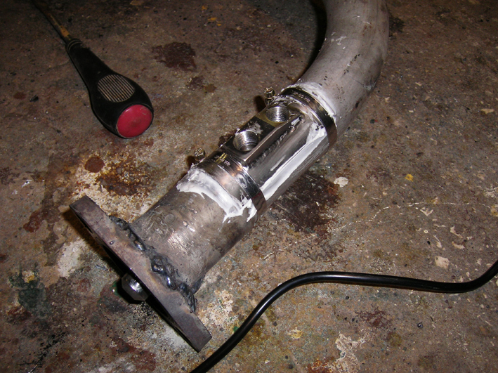
A beautiful new stainless steel pipe for the ocasion (the welder found hard the stainless steel welding flange) : Cheesy:

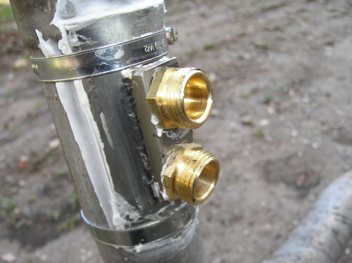
what is the motivation, to reduce the copper output duct bubbler? (easier to bend?) Good desicion, I also decreased the diameter on me montages for other reasons
The bubbler is of original construction, to watch if it is resistant to the pressure of the hot LDR (it would be a nuisance to miss ldr to make an antifreeze leak even if these engines have a cast iron head do not peter the seal breech)

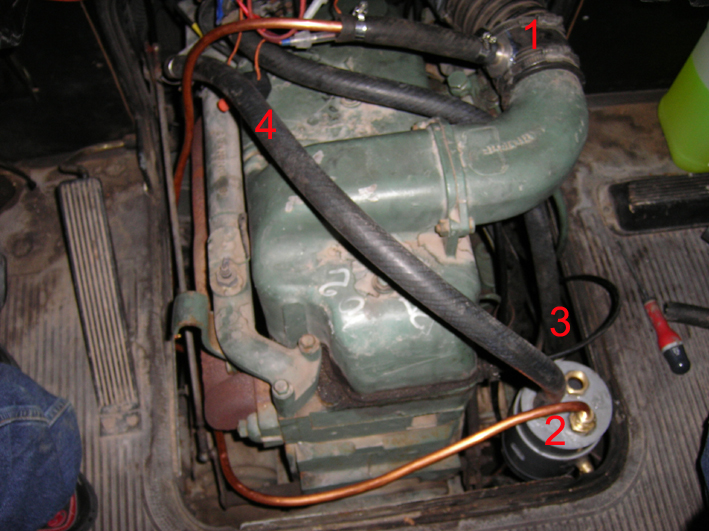
Why did you add a transparent hose in the inlet manifold inlet? to see the steam circulating in the duct
in sustained operation and load it becomes hot in this conduit

the bubbler duct (and given the little available place it has become long) it would be preferable to insulate it with a commercially available foam cover for water pipe that avoids internal condensation.
For depression if you want more it takes a venturi in the admission and avoid having a level too high in the bubbler

For the consumption test the yield is lower when you walk to oil 100% oil I have more than a liter of differrence

The engine is installed in a 5 vans manual gearbox
which consumes more than a car
these engines are around 2400rpm that are the most economical
On a 300D turbo engine 3 liters 125hp automatic gearbox that consumed before panton of 9,5 liters to 100km sometimes 10litres to 120kmh ..
the problem in the tests before doping with water was 90km which was at its best now it is at 110kmh which is at its best ..
In this reactor the central stem is tubular or they have put an internal baffle ..
Good tests ..

Andre
0 x
jime
Éconologue good!
Éconologue good!
posts: 215
Registration: 25/01/08, 18:53
Location: Var - Ardeche


by jime » 26/01/08, 08:27

hi andre

in fact I switched to a lower copper section with the intention of increasing the suction in the bubbler, and it is true that it is easier to bend I am currently in 8x10, but according to the guy of hypnow, it is better to shoot in 12x14 or 14x16
as the system is sold for tractors, I thought it needed more suction to make it work, error

the bubbler is completely traversed by the LDR, a hose from one side to the other, so the LDR is not likely to leak in case of rupture of the bubbler
Moreover, as soon as I have a little time, I will try to make a stainless steel

the transparent hose is provisional, it is just to see the system running, the air intake pipe from the reactor to the engine is arranged at 90 ° on the engine fan path, I hope that the temperature in this pipe will be limited

for the insulating foam, I noticed that too, comparing to the plans of aptitude, they also advise to isolate the departure of the bubbler, what I will do, otherwise the water supply pipe of the reactor runs along the engine then the exhaust from the bubbler, so once isolated I guess the nearby engine heat will prevent too high temperature drop

in the reactor, the central rod is tubular, the water makes a return trip from one end to the other after passing through the entrance to reach the exit

thanks for these tips i'm going to test
0 x


  • Similar topics
    Replies
    views
    Last message

Back to "Water injection in the engines: the assembly and experimentation"

Who is online ?

Users browsing this forum : No registered users and 286 guests