machine drum washing impeller
-
Christophe
- Moderator

- posts: 79374
- Registration: 10/02/03, 14:06
- Location: Greenhouse planet
- x 11064
Here is some info / comparison on the possible technical solutions for generating current for a wind turbine (and therefore a tidal turbine or anything else "running"): http://www.otherpower.com/otherpower_wi ... ators.html
A) Vehicle Alternators
* Advantages: cheap, easy to find, pre-assembled.
Disadvantages: high rpms required, low power output, low friction output, slip rings need maintenance.
* Suitability for Wind Power: POOR
The biggest problem with using them is that they are designed to rotate at a very high speed. Even a small, seemingly fast windmill might do most of its work at 600 rpm, not nearly fast enough for a car or truck alternator. This means that it is necessary to do so, but it is necessary to avoid friction - a big problem with wind or water power, but not a problem with a gasoline engine. Check out how useful it can be for building a small gas-powered HERE.
A standard car or truck alternator is electromagnetic - meaning that some of the electricity produced by the unit must be used internally and sent to the frame. Alternators that use electricity to generate more efficient and more complicated. They are quite easy to regulate, however, since the magnetic flux can be changed by adjusting the field power.
Also, the brushes and slip rings wear out, requiring more maintenance. Car and truck alternators can also be rewound to produce power at lower speeds. This is done by replacing the existing stator windings with more turns of smaller gauge wire. This project is not for the faint of heart, but check our PRODUCTS page for the inexpensive booklet by Thomas Lindsay If you are interested. The booklet is invaluable for any alternator experimentor! Also, some alternator / electric motor shops may have the knowledge to do this for you.
B) Homemade Permanent Magnet Alternators
* Advantages: Low cost per watt of output, very efficient, huge power output possible, extremely sturdy construction
* Disadvantages: A time-consuming, somewhat complicated project, machining needed.
* Suitability for Wind Power: GOOD
Homemade Volvo Disc Brake PM Alternator, 800 Watts, $ 150!
Hugh Piggott in Scotland was the pioneer in building permanent magnet alternators from scratch. Much of our inspiration came from his designs. Thanks Hugh!
Our experiments have consistently shown that homemade PM alternators are the most powerful and cost-effective solution for building a wind generator. Their low-rpm performance is excellent, and at high speeds they can really crank out the amps thanks to their efficiency. Our more recent PM alternators have been based on Volvo disc brake assemblies, which are very sturdy and have thrust bearings built into the unit. Our larger units are "Disc" or "Axial" designs ... a flat plate of magnets rotating next to a flat plate of coils. Our smaller PM alternators are "Radial" designs, where the magnets are fastened to the outside radius of the armature. Since all alternators produce AC, the output must be converted to DC with bridge rectifiers for battery charging.
Our designs to date have been single phase for ease of construction. Three-phase alternators have some advantages, but they are somewhat more difficult to build.
With a 7 ft diameter prop, our Volvo brake designs can be more than 60 amps into a 12 volt battery in a 30-mph breeze - that's about 700 watts. We've seen the Volvo design peak at 100 amps during high winds! This gives these homebrew designs a big advantage over similar-sized inducing motors, which become inefficiently fast and top out at 20-25 amps output with a 7 ft. diameter prop.
Check out all of our alternator projects on our EXPERIMENTS page!
C) Induction Motor Conversion Alternators
* Advantages: cheap, easy to find, easy to convert, good low-rpm performance.
Disadvantages: power output limited by internal resistance, inefficient at higher speeds, machining needed.
* Suitability for Wind Power: OK
Armature converted with permanent magnets
A normal AC induction motor can be converted into a permanent magnet alternator at very low cost. Our experiments have shown that these conversions produce significant power at very low speeds, but become inefficiently faster at higher power levels.
An induction motor has a center core with no wires in it, just alternating plates of aluminum and steel (it will look smooth from the outside). If you have a groove in this center core to accept permanent magnets, the unit becomes a permanent magnet alternator! We sell super-powerful neodymium magnets that are shaped and polarized perfectly for this application - check our products page.
In practice, our wind generators made with these do quite well until they reach 10-20 amps of output. At this point, they become inefficient quickly - it takes a large increase in windspeed to make only slightly more power, and the rest is wasted as heat inside the unit. The induction motors are wound with wire that's simply too thin for generating large amounts of power. In our tests, DanB's PM induction motor conversion windmill peaks at around 25 amps in 30 mph winds, with a 7-foot diameter prop. By comparison, a 7-foot prop on an efficient PM alternator made from scratch gives peaks of 50-60 amps in similar winds! Converted motors also have the tendancy to "cog" when starting ... you can feel the resistance when you turn the shaft. This affects low-speed startup somewhat.
If the lesser output in high winds is acceptable to you, these units can make for a pretty easy wind generator project. Look for AC induction motors of the lowest rpm rating possible. 3-phase motors will perform better than single phase. Since alternators produce alternating current (AC), the power must be converted to DC with bridge rectifiers.
Tips and photos - converting an AC induction motor into a permanent magnet alternator.
D) DC Generators
* Advantages: Simple and pre-assembled, some are good at low rpm.
* Disadvantages: High maintenance, low power, low power, small size.
* Suitability for Wind Power: POOR to OK
Generators make DC current and batteries need DC for charging. Generators have been used in automobiles until around 1970, when alternators became more practical (due to the availability of cheap, small diodes). Even old generators must be too much to be practical for wind power, but there are many good plans for modifying them. Check out our PRODUCTS page for the LeJay Manual, which contains many useful, but involved, plans for doing this. Generators are fairly complex compared to alternators. They must have brushes, and complex switches. Brushes require maintenance, and switches can wear out. For most purposes, generators do not have certain advantages at times. Some low rpm DC motors can be purchased as surplus and work as 12 volt low rpm generators. These are from old mainframe computer tape drives, and are sometimes available in local and electronic mail-order stores, and on Ebay. Check out our tape drive motor HERE page. They do not make a whole lot of power ... you can expect only 100-200 watts of output ... but these motors are almost a science project in a box! Slap on a frame and a 3-4 ft prop, and you have a small working wind generator.
Surplus tape drive motors can make a quick and easy generator for small windmills
E) Brushless DC PM Servo Motors
A brushless DC permanent magnet motor is really just a permanent magnet alternator! A special driver circuit provides AC power that is in phase with the rotation. If you are able to find a large one of these surpluses, it's possible you have an excellent start for a wind power project. They are used in robotics and precision control applications, and some use Nd-Fe-B magnets for high torque in a small space. As with surplus tape drive motors, we would like to see you in the future.
We have not yet been able to locate any of these surplus for experimentation. If you have had this information, please contact us! However, we do not have a small version of our product. We have a small surplus brushless DC PM motor, which is available for our products.
Inside a DC brushless DC motor
The inside of our tiny Brushless PM DC Motor looks just like the Wood 103's alternator!
F) Induction Motors as Alternators
It's possible to make a 3-phase induction motor produce electricity, either 3-phase or single phase. This requires a controller and capacitor. The generator must run at a fairly constant speed. For this reason, this type of generator is more suitable for constant-speed hydro power installations than for wind, where speed varies - though it can be done. We have not experimented with this technique yet, since we have a suitable hydropower source. For more information, check out the book Motors as Generators for Micro-Power Power by Nigel Smith.
0 x
Do a image search or an text search - Netiquette of forum
-
Christophe
- Moderator
- posts: 79374
- Registration: 10/02/03, 14:06
- Location: Greenhouse planet
- x 11064
I have temporarily solved the problem of the alternator!
Tigger has recovered an old wind turbine and is ok to lend it a few months, time to do a full-scale test!
I will finally be able to test my next toy: https://www.econologie.com/forums/post103307.html#103307

Tigger has recovered an old wind turbine and is ok to lend it a few months, time to do a full-scale test!
I will finally be able to test my next toy: https://www.econologie.com/forums/post103307.html#103307
0 x
Do a image search or an text search - Netiquette of forum
-
Christophe
- Moderator
- posts: 79374
- Registration: 10/02/03, 14:06
- Location: Greenhouse planet
- x 11064
I thought about the principle of the assembly a bit and here is the "principle diagram" which came out.
I'm looking for a design that is as simple, as "light" and as inexpensive as possible ... In short, something really eco-friendly and not something at € 2000 that never pays for itself! In short, I'm looking for African design!
My specifications for a useful power from 200 to 300W:
a) Max budget: 500 € in case I have to take the new alternator (probably on a small wind turbine from 2 to 400W)
b) Drum axis adjustable in height so that it can adapt to the water level of the watercourse.
c) The triangle of the main frame would therefore be mounted on a pivot (pins or bolts to tighten / loosen) and with on the downstream side (to compensate for the counter torque and gain stability) of the structure is a "buttonhole" with X holes adjustments or a slide system with friction tightening. To see the simplest, probably the buttonhole.
d) The rest of the chassis would be welded. I do not know if I would do it all in steel or aluminum. Probably steel recovery (even under water it should take a few years if the thickness is sufficient).
e) The whole thing would be stabilized by ... the stones of the stream that I will put on the lower profiles, even if I want to extend them if necessary.
f) I did not represent the turnbuckle because I do not know yet how to do it.
g) 2 bearings or plain bearings made of bronze to buy for the main axis of the drum which would be, as in a washing machine cantilever complete! Notice to the amateurs if you have some recovery! I'm interested! The axis should be well dimensioned since the motor of the machine in question made 380W ...
What do the mechanical design specialists think about it (which I will not quote for not favoritism! )? It's been almost 10 years since I did more mechanical design ...

I'm looking for a design that is as simple, as "light" and as inexpensive as possible ... In short, something really eco-friendly and not something at € 2000 that never pays for itself! In short, I'm looking for African design!
My specifications for a useful power from 200 to 300W:
a) Max budget: 500 € in case I have to take the new alternator (probably on a small wind turbine from 2 to 400W)
b) Drum axis adjustable in height so that it can adapt to the water level of the watercourse.
c) The triangle of the main frame would therefore be mounted on a pivot (pins or bolts to tighten / loosen) and with on the downstream side (to compensate for the counter torque and gain stability) of the structure is a "buttonhole" with X holes adjustments or a slide system with friction tightening. To see the simplest, probably the buttonhole.
d) The rest of the chassis would be welded. I do not know if I would do it all in steel or aluminum. Probably steel recovery (even under water it should take a few years if the thickness is sufficient).
e) The whole thing would be stabilized by ... the stones of the stream that I will put on the lower profiles, even if I want to extend them if necessary.
f) I did not represent the turnbuckle because I do not know yet how to do it.
g) 2 bearings or plain bearings made of bronze to buy for the main axis of the drum which would be, as in a washing machine cantilever complete! Notice to the amateurs if you have some recovery! I'm interested! The axis should be well dimensioned since the motor of the machine in question made 380W ...
What do the mechanical design specialists think about it (which I will not quote for not favoritism!
0 x
Do a image search or an text search - Netiquette of forum

For having recently changed my washing machine bearings, I have two ideas:
1 ° You speak of axis in complete cantilever; Does the drum axis of a top-loading MALL Top do not rotate around two bearings on either side of the drum?
This configuration seems intuitively better for a good balance. Balance that you will otherwise be forced to get through a heavy chassis or at least well secured.
2 ° In your description I understand that you disengage the drum from its cage which, I recall, is the support axis bearings. I therefore submit the idea of keeping intact the drum / cage assembly, which allows you to keep the existing bearings (preferably sealed), as well as the drive pulley of the belt that connects the motor to the drum.
You can cut into the cage two large slots, one in the upper position to channel water and the other in the lower position to evacuate, which, in passing, avoid a counter current.
It remains to think about transforming your drum into a paddle wheel without the latter rubbing against the cage; I therefore suggest that you cut your drum longitudinally at regular intervals and fold the "slats" thus cut towards the inside of the drum to form blades which are not turned towards the outside but towards the inside. The only problem I see there may be that posed by the multiple holes of the drum, the water entering partly into the drum through these holes may slow it down. But if this is confirmed, it may be possible to close the said holes.
What might look like this roughly:

What do you think ?
1 ° You speak of axis in complete cantilever; Does the drum axis of a top-loading MALL Top do not rotate around two bearings on either side of the drum?
This configuration seems intuitively better for a good balance. Balance that you will otherwise be forced to get through a heavy chassis or at least well secured.
2 ° In your description I understand that you disengage the drum from its cage which, I recall, is the support axis bearings. I therefore submit the idea of keeping intact the drum / cage assembly, which allows you to keep the existing bearings (preferably sealed), as well as the drive pulley of the belt that connects the motor to the drum.
You can cut into the cage two large slots, one in the upper position to channel water and the other in the lower position to evacuate, which, in passing, avoid a counter current.
It remains to think about transforming your drum into a paddle wheel without the latter rubbing against the cage; I therefore suggest that you cut your drum longitudinally at regular intervals and fold the "slats" thus cut towards the inside of the drum to form blades which are not turned towards the outside but towards the inside. The only problem I see there may be that posed by the multiple holes of the drum, the water entering partly into the drum through these holes may slow it down. But if this is confirmed, it may be possible to close the said holes.
What might look like this roughly:
What do you think ?
0 x
-
Christophe
- Moderator
- posts: 79374
- Registration: 10/02/03, 14:06
- Location: Greenhouse planet
- x 11064
Thanks for those 1ere reactions.
Yes but the drum I have is loading by the side ...
So already cantilevered and that has only one axis!
For me too, but I think that the efforts will be less important than on a washing machine loaded with spinning laundry! And nothing prevents me to oversize the landing ...
Oh no, I just want to keep the original axis, the pulley and the belt if possible (I recovered the 3) ... and I will "cut" the blades directly in the drum ...
Uh ... I see but do not go outside according to you? Deformation? One or 2 small squares will do no?
Ben saw how the drum will be cut I do not think a lot of water stagnates inside!
Oula is a real mill ca! ... It's not the idea, I wanted a removable thing and that works more with the flow rate than the height ... Now if this 1ere idea does not go (or not enough powerful) I could consider doing something like that since I have a hold 40 cm of the belier ... but it's more work and investment ...
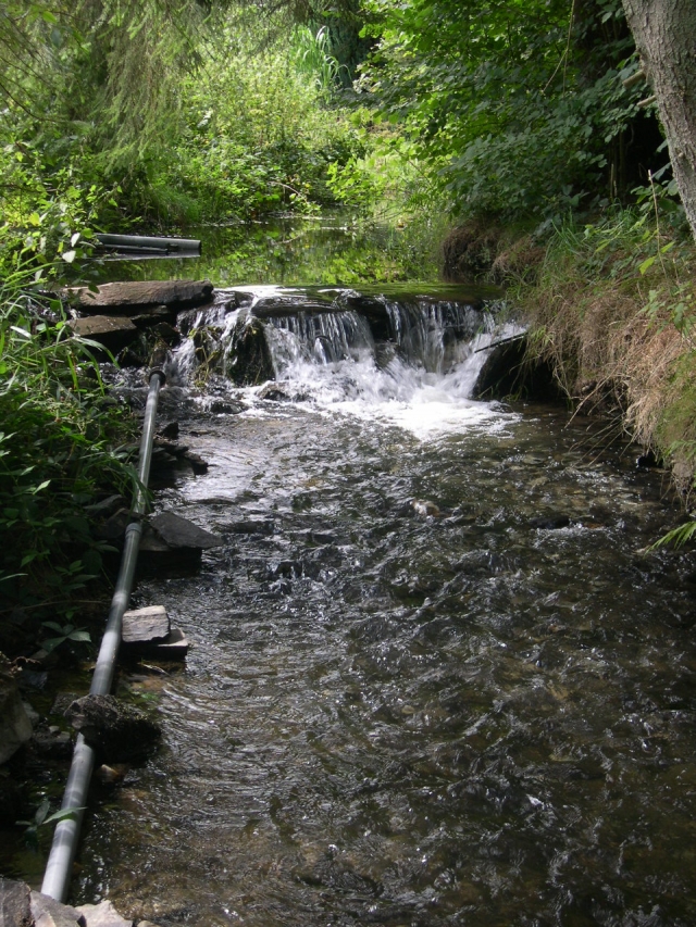
Here is the "dam" in question:
bham wrote:1 ° You speak of axis in complete cantilever; Does the drum axis of a top-loading MALL Top do not rotate around two bearings on either side of the drum?
Yes but the drum I have is loading by the side ...
So already cantilevered and that has only one axis!
bham wrote:This configuration seems intuitively better for a good balance. Balance that you will otherwise be forced to get through a heavy chassis or at least well secured.
For me too, but I think that the efforts will be less important than on a washing machine loaded with spinning laundry! And nothing prevents me to oversize the landing ...
bham wrote:2 ° In your description I understand that you disengage the drum from its cage which, I recall, is the support axis bearings. I therefore submit the idea of keeping intact the drum / cage assembly, which allows you to keep the existing bearings (preferably sealed), as well as the drive pulley of the belt that connects the motor to the drum.
Oh no, I just want to keep the original axis, the pulley and the belt if possible (I recovered the 3) ... and I will "cut" the blades directly in the drum ...
bham wrote:It remains to think about transforming your drum into a paddle wheel without the latter rubbing against the cage; I therefore suggest that you cut your drum longitudinally at regular intervals and fold the "slats" thus cut towards the inside of the drum to form blades that are not turned towards the outside but towards the inside.
Uh ... I see but do not go outside according to you? Deformation? One or 2 small squares will do no?
bham wrote:The only problem that I see there can be that posed by the multiple holes of the drum, the water entering partly into the drum by these holes likely to stop it.
Ben saw how the drum will be cut I do not think a lot of water stagnates inside!
bham wrote:But if it is confirmed, it may be possible to close the said holes.
What might look like this roughly:
https://www.econologie.info/share/partag ... aLvRHF.png
What do you think ?
Oula is a real mill ca! ... It's not the idea, I wanted a removable thing and that works more with the flow rate than the height ... Now if this 1ere idea does not go (or not enough powerful) I could consider doing something like that since I have a hold 40 cm of the belier ... but it's more work and investment ...
Here is the "dam" in question:
0 x
Do a image search or an text search - Netiquette of forum
Christophe wrote:bham wrote:It remains to think about transforming your drum into a paddle wheel without the latter rubbing against the cage; I therefore suggest that you cut your drum longitudinally at regular intervals and fold the "slats" thus cut towards the inside of the drum to form blades that are not turned towards the outside but towards the inside.
Uh ... I see but do not go outside according to you? Deformation? One or 2 small squares will do no?
Because if the blades are turned outwards they will come into contact with the cage, which makes me say that you did not understand my idea: it is to keep the cage (I do not really know the name) ) in stainless steel in which the drum rotates; the clearance between cage and drum is quite small (2 / 3 cms), which limits the possibility of making external blades
Christophe wrote:bham wrote:What might look like this roughly:
https://www.econologie.info/share/partag ... aLvRHF.png
What do you think ?
Oula is a real mill ca! ... It's not the idea, I wanted a removable thing and that works more with the flow rate than the height ... Now if this 1ere idea does not go (or not enough powerful) I could consider doing something like that since I have a hold 40 cm of the belier ... but it's more work and investment ...
I just wanted to illustrate the fact of "internal" blades.
0 x
-
Christophe
- Moderator
- posts: 79374
- Registration: 10/02/03, 14:06
- Location: Greenhouse planet
- x 11064
Uh the cage is the strapping around? I do not understand the conflict with the blades and it will be preserved, what prevents it?
I intended to leave 1 cm on each side by cutting the "vanes" and 2 to 3 cm between each vane.
If the torsional strength of the assembly becomes insufficient, nothing prevents to weld or assemble inside the drum (thanks to my mig ) some reinforcing elements!
I forgot something: a non inertia disk? (possibly integrate it on the paddle wheel with weights?
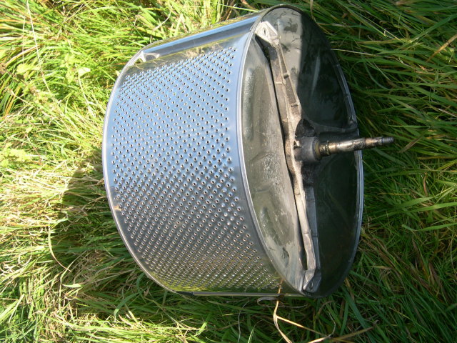
Here is the picture of the drum that I have:
I intended to leave 1 cm on each side by cutting the "vanes" and 2 to 3 cm between each vane.
If the torsional strength of the assembly becomes insufficient, nothing prevents to weld or assemble inside the drum (thanks to my mig
I forgot something: a non inertia disk? (possibly integrate it on the paddle wheel with weights?
Here is the picture of the drum that I have:
0 x
Do a image search or an text search - Netiquette of forum

Hello
For those who wish to provide or have information on alternators adapted to low speeds of rotation here are some links:
http://www.windbluepower.com/
http://www.futurenergy.co.uk/turbine.html
Otherwise you can always change a car alternator with permanent magnets
https://www.econologie.com/forums/alternateu ... t4674.html
My proto has a 20 diameter output shaft, and outputs 12V to 240 rpm
A+
0 x
Christophe wrote:Uh the cage is the strapping around? I do not understand the conflict with the blades and it will be preserved, what prevents it?
Here is the picture of the drum that I have:
I understand that we have trouble understanding each other
0 x
Back to "hydraulic, wind, geothermal, marine energy, biogas ..."
Who is online ?
Users browsing this forum : No registered users and 164 guests